Validating SOPs for GMP Cannabis

The objective of validating a procedure is to demonstrate that the procedure is suitable for its intended purpose. This extends to all SOPs. They must be validated to prove that they accomplish their purpose. There are many different processes that can be validated in pharmaceutical operations. Some examples include, but are not limited to, process chemistry, analytical testing, lab facilities, cleaning, equipment, packaging, etc.

For the sake simplicity, this article will cover validation of analytical methods. Method development and validation are all about setting specifications and making sure that the method can reliably achieve those standards. The specifications are discovered during method development, where an analyst works by trial and error to find the right conditions, that are described by example below. It is a tedious process, but once the proper method for analysis is established (i.e. the right column, the right flow rates, the right wavelength, and right temperatures), you have data that should show a reproducible method. From there, it’s a matter of setting the amount of variance that is tolerable to still accomplish the method (i.e. validation parameters).

Analytical method development is the time when the robustness of a method is established. Robust in this sense, means that you can change parameters of the method without seeing variation in the results – that is, despite conditions being less than optimal, you still get good results. Validation checks the variation in methods – you must get the same results for a given method within a specified percentage or relative standard deviation. If a method has been proven to be robust, it has a much greater chance of passing validation (being within the specified variance).

There are three major types of analytical methods: identity tests, assays, and impurity tests. An identity test proves that a certain molecule is present in a sample. An assay shows how much of a molecule is present in a sample. An impurity test shows how much of the sample has degraded or the relative quantities of impurities present in a sample. There are 6 major parameters tested in the validation of analytical methods: accuracy, precision, specificity, detection limits, quantification limits, and range.

Validation parameters require qualified reference standards. Ideally they will be from a third party, manufactured in an ISO environment that ensures the purity. The qualified reference standards are how meaningful comparisons are made to assess each parameter.

  • accuracy – how close to the target value the method reliably achieves
  • precision – how close each measurement is to the other measurements in a series of measurements
  • specificity – identification of the exact molecule that’s being tested – i.e. the method can discriminate between molecules similar to the target molecule.
  • detection limit – the smallest quantity of a molecule that can be detected
  • quantification limit – the smallest quantity of a molecule that can be reliably quantified
  • range – the smallest and largest amount of a molecule that can be reliably quantified in an analytical test

Details of the method should be clearly listed and explained in the validation report. They are important because they clearly lay out the conditions to execute a given method. Here are a few examples of method conditions:

  • Description of the method – e.g. HPLC
  • Type of chromatography column – e.g. C18 Reverse Phase HPLC Column
  • Flow rate and method durations – e.g. 1mL/min – 20 min runtime
  • Detection Wavelength – e.g. 210nm
  • Column Temperature – e.g. 30C

If you have more questions, check out www.oriongmp.com and get a free consultation on putting together your Cannabis related Good Manufacturing Practices and Quality Manufacturing Systems.

This question was asked in the comments section in cannabis extracts in Reddit – how do you produce pure Δ9 THC that’s appearing in dispensaries??? A fellow named Adam Mueller answered this question, and figured out the sub/supercritical conditions to produce pure Δ9 THC and was issued a patent for it last year.

It is also possible to extract and purify THC to a high concentration using other methods. However, they mostly use solvents that are known to be carcinogenic. CO2, on the other hand, defines a “Green Solvent” – no carcinogenicity, and no waste products that pollute the environment.

Patent: US 2014/0248379 – Process for producing an extract containing THC and CBD from cannabis plant material, and cannabis extracts.

Adam Mueller has several patents describing the extraction of cannabinoids from hemp and drug varieties of cannabis. He represents Delta-9-Pharma GmbH, a company out of Germany. While this information may not be novel to people who are already performing extracts, it is of interest to people who would like to learn about the conditions.

This patent explains the steps from taken from grinding up plant matter, subjecting it to subcritical or supercritical conditions and producing a pure CBD and THC product. An interesting point is that CBD can be converted to THC with the right conditions. Past that, the product is dewaxed and ready for delivery in the activated decarboxylated form.

There are some aspects of the patent that are very useful, but there are downsides to running supercritical CO2, given what we know about the “entourage effect” described by Ethan Russo (1). Cannabinoids alone do not have the highest medicinal benefits as a mixture terpenes and cannabinoids. While this patent describes a way to obtain highly purified CBD and THC, the terpenes end up in a separate fraction. Recombining THC, CBD, and terpenes is not unheard of, but it does require a bit more work.

Raw materials

Mueller’s primary source of raw materials is hemp. This is a logical starting material for countries where it is illegal to cultivate marijuana. For the validation of the patent, he used five different strains that are from French, Hungarian, and Finnish origins. In general, these are industrial hemp varieties that are used for fiber production. The legal requirements for such strains are that they contain no more than 0.3% THC by dried weight of the starting materials.

Sub/Supercritical conditions

Mueller provides a range of conditions that can be used to extract cannabinoids with supercritical CO2. Supercritical conditions range from 31-80℃ and 75-500 bar. Subcritical conditions range from 20-30℃ and 100-350 bar.

Subcritical and supercritical extracts do not come out with the same consistencies. Subcritical extractions preserve more terpenes, while supercritical extractions lose terpenes and increase the waxes. Subcritical extracts have an oil like consistency, have less plant lipids (waxes), and may not need dewaxing, depending on the application and what customers want – it is nearly ready for use in vape pens or to be dabbed. Supercritical extracts have a more solid “crumble” consistency, have more plant lipids, and most certainly require dewaxing in order to be used in vape pens or dabs. Both can be used for edibles.

A follow up point is that both subcritical and supercritical runs can be done on the same starting material. First perform a subcritical run and collect the extract – the extract will still have some terpenes present without being overwhelmed with waxes. Then, the same starting material can be run a second time under supercritical conditions. Running subcritical conditions produces relatively low yields, so to maximize yield (i.e. profitability) one really needs to run supercritical conditions. You may find the extra work of doing two runs is not worthwhile, considering you have to have to do twice the work. There’s always a trade-off somewhere in a process, and this one is for you to decide. For maximum yield, Mueller suggests performing two runs on the same material.

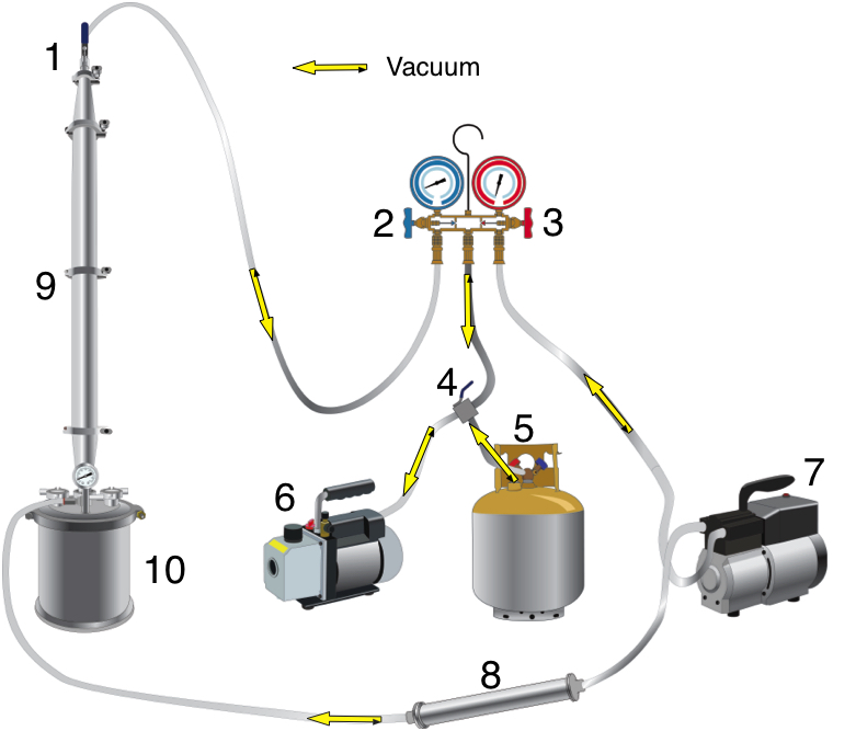
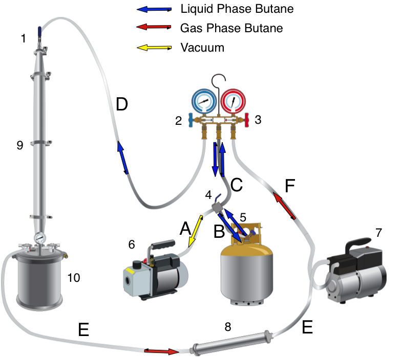
Mueller increases yields by using “entraining agents.” Butane, propane, and ethanol are used in concentrations of 1-10%.

Entraining agents have different properties than supercritical CO2. The critical point (CP) of CO2 is 73.8 bar and 31.5℃; butane has a CP of 38.0 bar and 152 (2); propane’s CP is 42.5 bar and 96.7C (3); ethanol’s CP is 63 bar and 241. A mathematical description requires computational chemistry to show how the entraining agents interact with the CO2. Suffice it to say, CO2 will be in the supercritical phase and the entraining agents will be in the liquid phase (3), (4). This changes the solvent characteristics of the CO2 and improves extraction yields.

His optimal supercritical conditions range from 45-65, 100-350 bar, with his best conditions being 60C and 250 bar. His preferred subcritical conditions range from 20-30 and 100-350 bar.

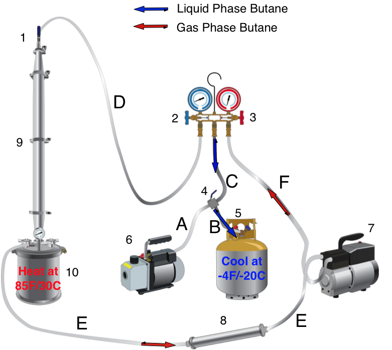
Mueller illustrates the system in figures 1-3. It’s a complicated system that is appropriately named a “CO2 extraction plant.” This system was designed for process scale. The system has three components: the extraction system (figure 1), the CBD cyclization system (figure 2), and the CBD/THC separation system (figure 3).

How CO2  supercritical work – solubility

Figure 1

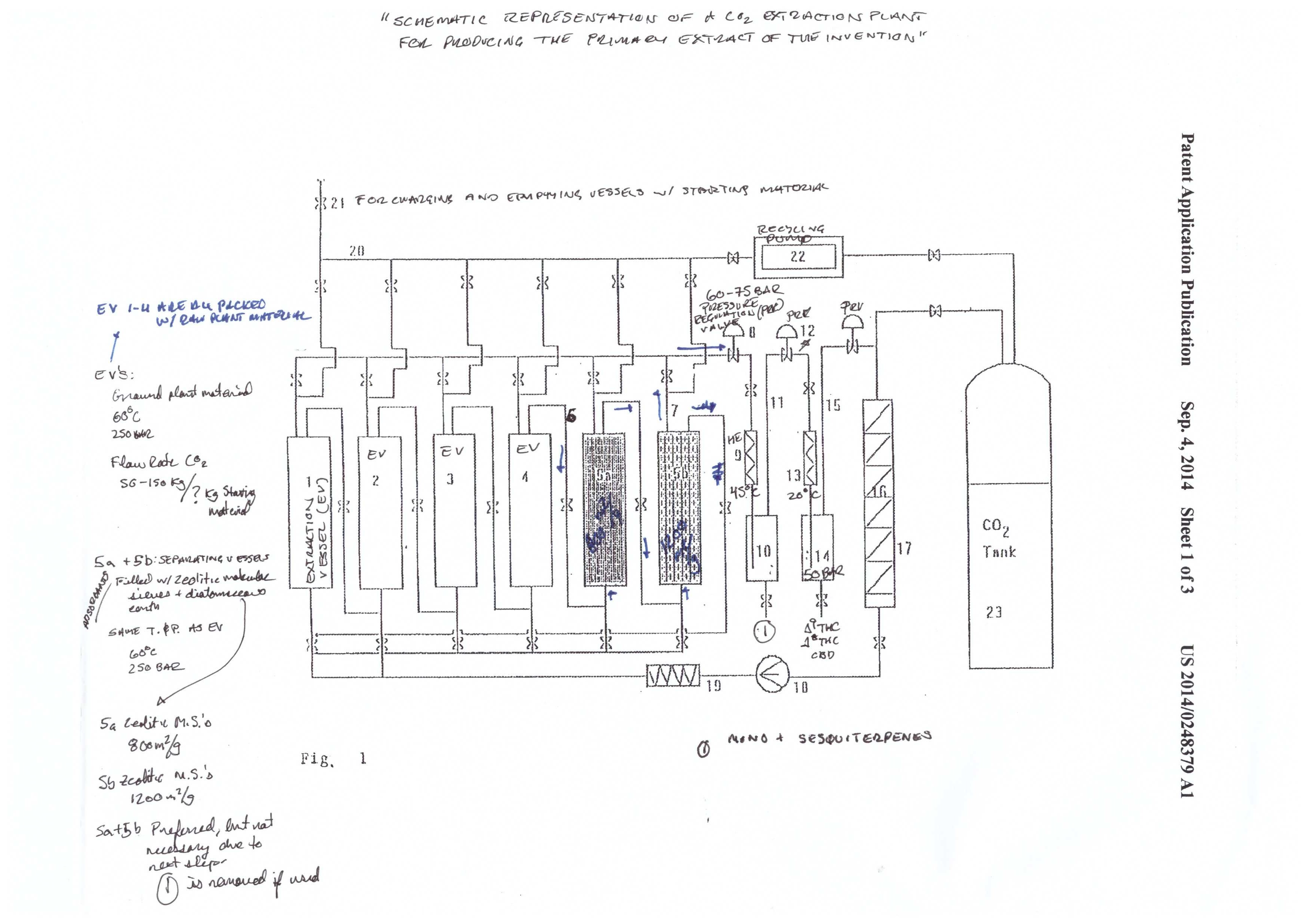
The extraction starts in the extraction vessel (F1: 1-4). The column(s) is packed with plant material, and the sub/supercritical CO2 begins to strip the plant material of cannabinoids. The cannabinoids are called the solute, and the CO2 is called the solvent. A solvent becomes saturated when it has no more “room” for more solutes to be carried by the solvent.

The cannabinoid saturated solvent then passes into the separating vessels (F1: 5a-5b) in a continuous process. Fresh solvent enters the extraction vessel, dissolves cannabinoids and other phytochemicals, and carries them into the separating vessels. The cannabinoids are the first solutes to pass through the separating vessels, followed by terpenes, and then the undesirable phytochemicals.

The order of the solutes entering the separating vessel (packed with adsorbents) is dependent on how strong of an interaction each molecule has with the adsorbent media. Cannabinoids have the weakest interaction (first out) and the undesirable phytochemicals have the strongest (last out).

The solubility of the different solutes in the solvent depends on both pressure (P) and temperature (T). The general scheme of the system is to go from high P to low P, and high T to low T, in graduated steps. At high P and T have the highest solubility.

As the P and T are reduced, the solubility of certain components is reduced. For example, the extraction vessels and separating vessels run at 60℃ and 250 bar. The terpene/cannabinoid rich solvent is then pumped over to the first collection vessel (10), at 45℃ and 60-75 bar. That reduction in P and T causes the terpenes to fall out of solution. Meanwhile, the cannabinoids are still in solution.

The cannabinoids are then pumped to the next collection vessel (14). T and P are reduced to 20℃ and 50 bar. Under these conditions, the cannabinoids fall out of solution, and are ready for collection.

Dewaxing and decarboxylation

Dewaxing is pretty standard in the industry these days. Unless you run very cold conditions, you’re going to pick up wax in both hydrocarbon and CO2 extractions. To put it simply, cold ethanol is used to dissolve the extract, followed by freezing and filtration. The extract can then be moved on to decarboxylation, which is a well documented process in the industry.

Converting CBD to THC

Figure 2

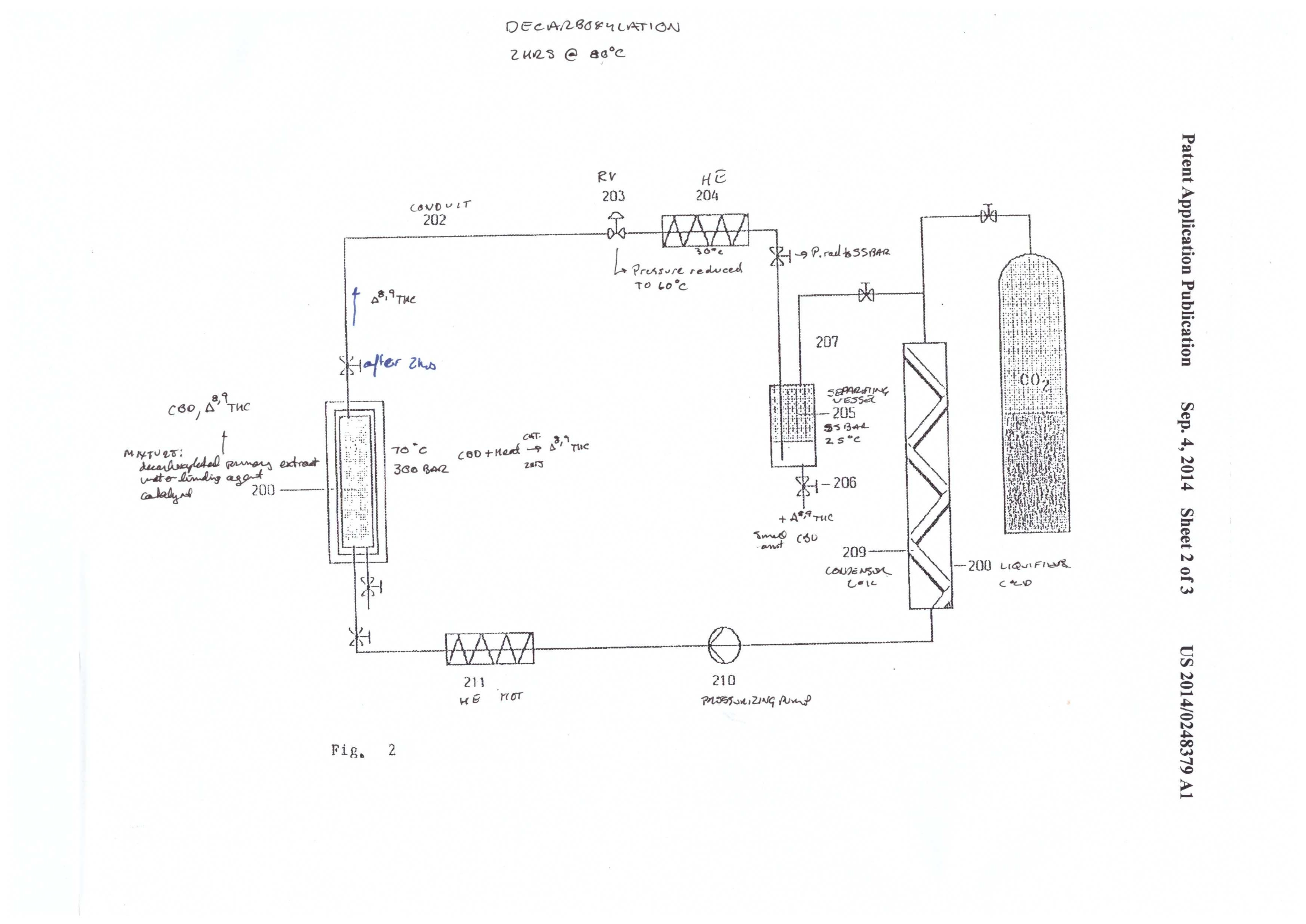
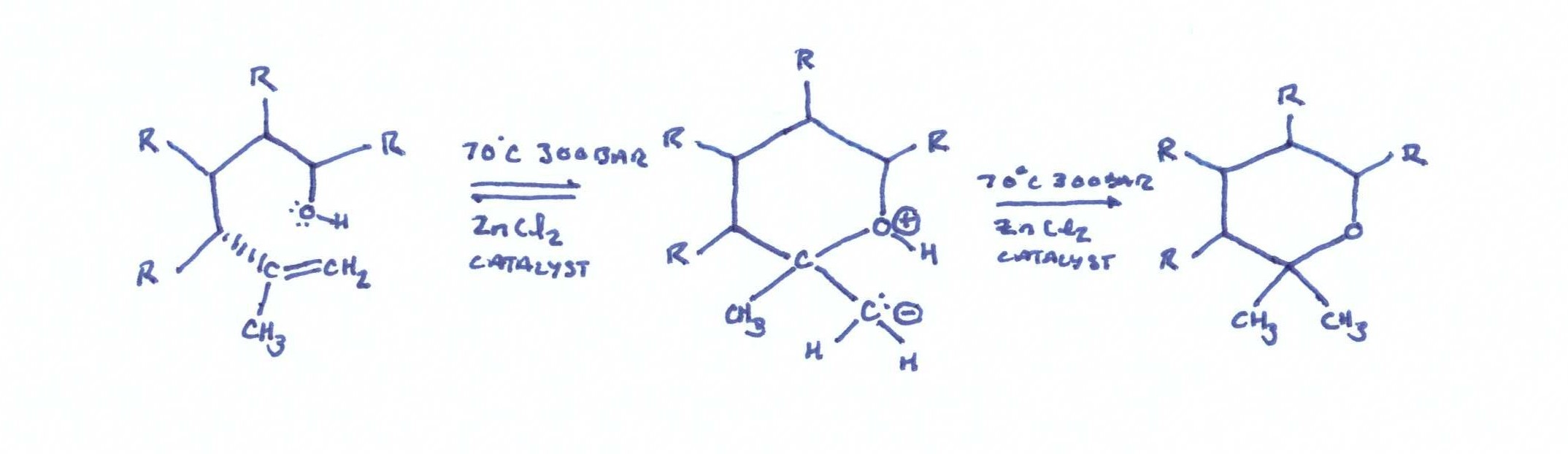
The second admirable part of this patent is the cyclization reaction of CBD to THC. Molecular/zeolytic sieves and zinc chloride are employed as a catalyst to aid the reaction. The molecular sieves act as a water binding agent, and the zinc chloride acts as a catalyst to reduce the activation energy required for the cyclization reaction.

The conditions are 300 bar and 70℃, and the reaction takes place over a 2 hour time period. The apparatus in figure 2 shows a simple reaction vessel containing the catalysts and extract that are plumbed to a separate collection vessel. The extract is pumped out to the collection vessel by precipitation with 55 bar and 25℃.

CBD THC reaction

Pure ΔTHC

Figure 3

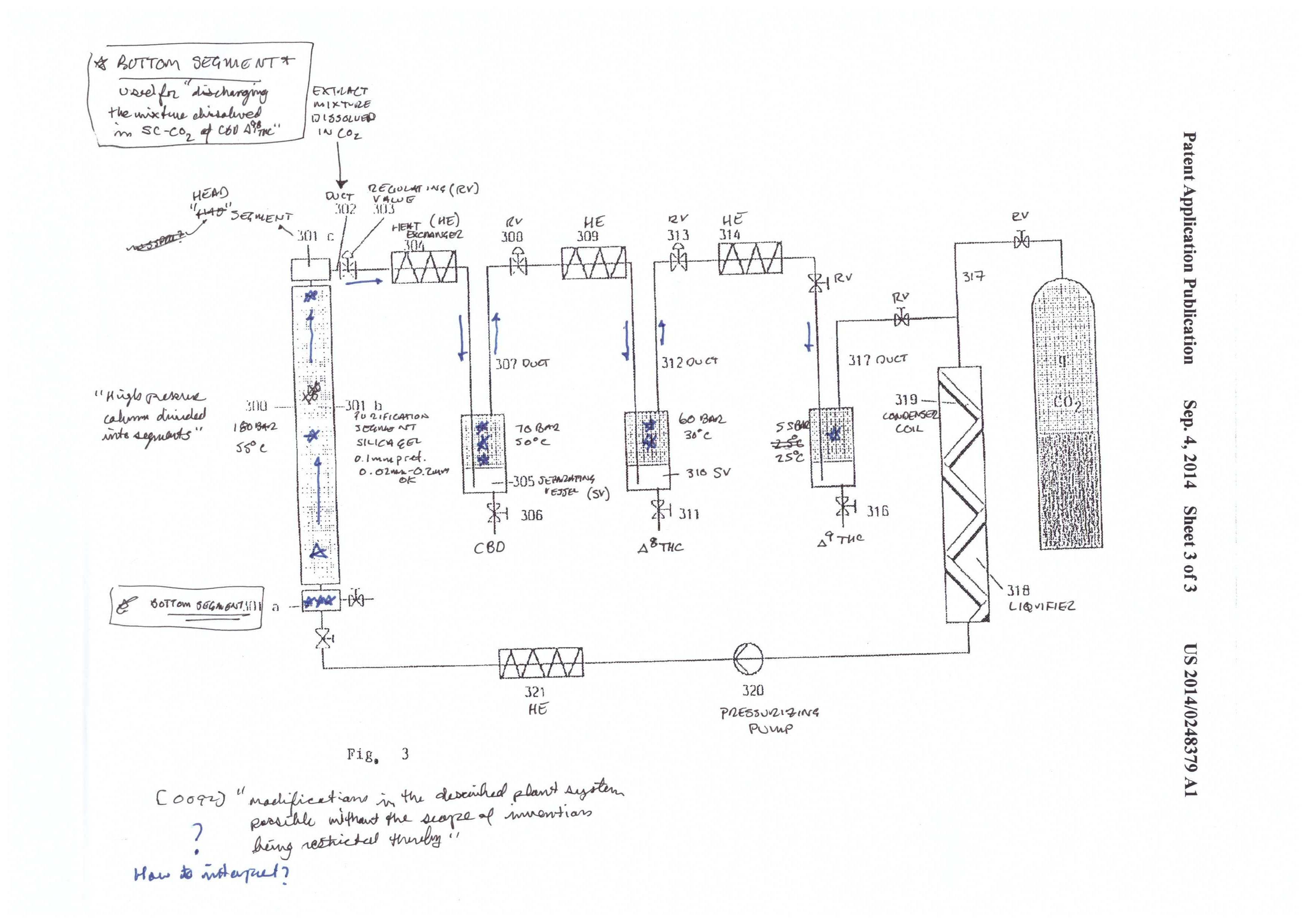
The final step described in the patent is the separation of CBD, ΔTHC, and ΔTHC. This is achieved by using a purification material/media commonly used in separation science – silica. As is described below in the chromatography, silica has a charge to it, that reacts with the molecules that are to be separated/purified from one another. Some molecules have a stronger interaction than others and therefore travel slower through the silica packed column. In this case, Mueller ends up with pure fractions of the three cannabinoids.

The silica used in the patent has an average size of 0.1mm, and is commonly used in separation science. Looking at figure 3, you will see that the CBD/THC mixture starts at the bottom of the column. When the supercritical CO2 is pumped into the system, the mixture travels up the column and begins to separate the mixture.

After the separation column, there are three collection vessels. As with the initial extraction, CBD, ΔTHC, and ΔTHC are separated out by precipitation. The precipitation occurs from dropping the P and T in steps from high to low. CBD is precipitated at 70 bar and 50℃. ΔTHC is precipitated at 60 bar and 30℃, and ΔTHC is precipitated at 55 bar and 25℃.

Separation of plant phytochemicals, terpenes, and cannabinoids

The  first step in this patent produces pure THC/CBD while removing the plant alkaloids, flavonoids, and chlorophyll. It also removes terpenes.

Without good separation/purification, the terpene fraction can be contaminated with plant alkaloids, flavonoids, and chlorophyll. This is one of the inherent downsides to CO2 extractions compared to butane extractions; phytochemical contamination can be reduced in butane extractions by keeping conditions at sub-zero temperatures. In CO2 extractions, it can be reduced by not cranking the extractor into “hyperdrive” conditions.

Although the loss of terpenes is an inherent problem with supercritical CO2, it’s easiest to preserve terpenes by performing a subcritical run followed by supercritical run. This maximizes the yields, but is not explicitly described as the method used in this patent – it only suggests that the materials are extracted a second time.

Adsorbents

The use of adsorbents is illustrated by way of a packed column in figure 1. An adsorbent is a substance that attracts molecules, and the molecules subsequently adhere to the surface. Note that this is not the same as absorbing, where a molecule is taken into the structure of the substance. An adsorbant has a transient interaction with the molecules it attracts, where the molecules stay on the surface. An absorbant actually soaks up a molecule into its pores, rather than just staying on the surface.

Adsorbents are used in this patent to remove undesirable molecules, such as alkaloids, flavonoids, and chlorophyll. The adsorbents attract undesirable molecules. They adhere to the surface under sub and supercritical conditions, temporarily falling out of the supercritical solution, while the terpenes and cannabinoids stay in solution and pass on to the next section of the system. It is a clever way to remove the undesirables, but is relatively common in separations science.

The adsorbents are silica gel, diatomaceous earth, bentonite, bleaching earth, activated carbon, and mixtures of magnesium oxide and alumina zeolitic. Although it’s not explicitly said, there are two ways that the adsorbents can be used. First, you can pack the plant matter on top of a bed of adsorbents. The second method is to have secondary column in-line, downstream of the extraction chamber, that pulls out all undesirables. The second is much more clean and efficient, but requires additional equipment, and at these kinds of pressure ratings, stainless steel is not cheap.

Chromatography

A more subtle point, that may not be immediately apparent, is the application of chromatography. Chromatography is loosely defined as the separation of mixtures. In this case, the mixture to be separated is the undesirable plant phytochemicals and the desirable terpenes/cannabinoids. The main function of chromatography media (i.e. adsorbents and silica) is to allow some molecules to travel through the media faster than others.

When a molecule has a strong interaction with the chromatography/purification media, it travels slower. When a molecule has a weak interaction, or is repelled by the media, it travels faster. Imagine each phytochemical being a molecular magnet. For example THC and CBD are very weak magnets compared to alkaloids, flavonoids, and chlorophyll. In fact, the undesirable molecules are like strong magnets.

The way this works, is that the adsorbents are also like strong magnets, but have the opposite charge of the undesirable phytochemicals. Opposites attract, and the undesirable phytochemicals are strongly attracted to the adsorbent, while the desireable terpenes and cannabinoids have a weak attraction to the adsorbent. The weaker the interaction, the faster the molecules can travel through the media, and vice versa.

Extraction, purification, and resolution in supercritical extractions

Extraction is the first step in any purification scheme. The industry is currently focusing on whole plant extracts, without much purification beyond dewaxing. This patent utilizes purification in the process – this is how CBD, ΔTHC, and ΔTHC are separated from each other.

As described above, chromatography is the mechanism of separating molecules. This can be done by columns packed with silica, and other packing materials. In chemistry, the packing materials are called purification media. Whatever packing material is used, the purpose is to slow down some of the molecules in order to separate the ones you want from the ones you don’t want.

You can’t talk about chromatography without talking about resolution. Resolution can be simply defined as the amount of separation of two molecules in a purification process. Depending on what kind of packing materials used, you can separate groups of molecules from one another. Some packing materials work better for some types of molecules, and is a chore to find the right media when starting a new purification scheme.

When you put together the extraction step and follow it with purification steps, you can separate groups of molecules. The choice of using purification is one that is dependent on whether one wants a pure product.

The end product

One really needs to ask themselves how important purity is. The more pure of a product desired, the more effort that is required. Do you really want pure crystalline THC and CBD? If yes, this process may be right for you. If you just want an extract, you may want to consider these steps, but take what information is useful to you.

Again, a process is only useful if it is economically viable. The extra effort spent in making pure products is significant, but is a daily reality in the pharmaceutical industry. A point to consider is that the closer you get to a pure product, the higher the chance of losing your product due to mistakes.

Having spent years in chemical purifications, plenty of solvent and product have been lost to simple, avoidable mistakes. To avoid mistakes, clearly define your process before you begin. Always have a plan and think about what you’re going to do before you execute the plan. Be careful, take your time, take good notes, and always keep the safety of the consumer as your top priority.

  1. http://www.ncbi.nlm.nih.gov/pmc/articles/PMC3165946/clopedie/VaporPressureGraph/Propane_Vapor_Pressure.GIF
  2. http://encyclopedia.airliquide.com/images_encyclopedie/VaporPressureGraph/Butane_Vapor_Pressure.GIF
  3. http://encyclopedia.airliquide.com/images_encyclopedie/VaporPressureGraph/Propane_Vapor_Pressure.GIF


When the extractor has been properly shut down, it’s time to disassemble it and reveal the cannabinoid alchemy you’ve performed, turning solid green plant matter into a concentrated liquid gold $)

Final image - Shut down

Step 7 – Extractor Disassembly – remove stainless steel hose (D) from extractor column valve (1)
Component #Component NameAbbreviationOpen/OnClosed/Off
1Extraction Column ValveECVx
2Low Pressure Recovery ManifoldRM2x
3High Pressure Recovery ManifoldRM3x
4Purge PortPPx
5Recovery CylinderRCx
6Vacuum PumpVPx
7Recovery PumpRPx
Step 7.1 – Extractor Disassembly – open extractor column valve (1) to allow air to enter extractor
Component #Component NameAbbreviationOpen/OnClosed/Off
1Extraction Column ValveECVx
2Low Pressure Recovery ManifoldRM2x
3High Pressure Recovery ManifoldRM3x
4Purge PortPPx
5Recovery CylinderRCx
6Vacuum PumpVPx
7Recovery PumpRPx
Step 7.2 – Extractor Disassembly – remove extraction column (11)
Component #Component NameAbbreviationOpen/OnClosed/Off
1Extraction Column ValveECVx
2Low Pressure Recovery ManifoldRM2x
3High Pressure Recovery ManifoldRM3x
4Purge PortPPx
5Recovery CylinderRCx
6Vacuum PumpVPx
7Recovery PumpRPx
Step 7.3 – Extractor Disassembly – remove extractor base from extractor collection vessel (12)
Component #Component NameAbbreviationOpen/OnClosed/Off
1Extraction Column ValveECVx
2Low Pressure Recovery ManifoldRM2x
3High Pressure Recovery ManifoldRM3x
4Purge PortPPx
5Recovery CylinderRCx
6Vacuum PumpVPx
7Recovery PumpRPx


As always, if you have any questions please post them in the comments section. Your questions and time are valuable and we will make every attempt to help you through your process.

Once the extraction collection chamber reaches the desired pressure under vacuum, it’s ready to shut down. Shut down always starts with stopping the flow of butane – i.e. turning off the recovery pump.

Final image - Shut down

Step 6 – Post Recovery Shut Down – turn off the recovery pump (7)
Component #Component NameAbbreviationOpen/OnClosed/Off
1Extraction Column ValveECVx
2Low Pressure Recovery ManifoldRM2x
3High Pressure Recovery ManifoldRM3x
4Purge PortPPx
5Recovery CylinderRCx
6Vacuum PumpVPx
7Recovery PumpRPx
Step 6.1 – Post Recovery Shut Down – close the recovery cylinder liquid side valve (5)
Component #Component NameAbbreviationOpen/OnClosed/Off
1Extraction Column ValveECVx
2Low Pressure Recovery ManifoldRM2x
3High Pressure Recovery ManifoldRM3xx
4Purge PortPPx
5Recovery CylinderRCx
6Vacuum PumpVPx
7Recovery PumpRPx
Step 6.2 – Post Recovery Shut Down – close the purge port (4)
Component #Component NameAbbreviationOpen/OnClosed/Off
1Extraction Column ValveECVx
2Low Pressure Recovery ManifoldRM2x
3High Pressure Recovery ManifoldRM3xx
4Purge PortPPx
5Recovery CylinderRCx
6Vacuum PumpVPx
7Recovery PumpRPx
Step 6.3 – Post Recovery Shut Down – close the high pressure recovery manifold (3)
Component #Component NameAbbreviationOpen/OnClosed/Off
1Extraction Column ValveECVx
2Low Pressure Recovery ManifoldRM2x
3High Pressure Recovery ManifoldRM3x
4Purge PortPPx
5Recovery CylinderRCx
6Vacuum PumpVPx
7Recovery PumpRPx
Step 6.4 – Post Recovery Shut Down – close the extraction column valve (1)
Component #Component NameAbbreviationOpen/OnClosed/Off
1Extraction Column ValveECVx
2Low Pressure Recovery ManifoldRM2x
3High Pressure Recovery ManifoldRM3x
4Purge PortPPx
5Recovery CylinderRCx
6Vacuum PumpVPx
7Recovery PumpRPx


As always, if you have any questions please post them in the comments section. Your questions and time are valuable and we will make every attempt to help you through your process.

After running the continuous shower, the liquid butane is pulled off into the gas phase by the recovery pump and pushed into the liquid phase, which then fills back into the recovery cylinder. The push/pull method of recovery requires heating the extraction collection vessel (10) and cooling the recovery cylinder (5). The recovery cylinder can be cooled to -50C if you use a dry ice/ethanol bath, but is not necessary – it just speeds up the recovery. Push/pull is governed by the most useful branch of chemistry – thermodynamics – we’ll explain that at a later time if anyone is interested…

Final image - butane recovery

Step 5 – Butane Recovery – heat extraction collection chamber (10) to 85F/30C; cool the recovery cylinder (5) to -4F/-20C; open the purge port (4)
Component #Component NameAbbreviationOpen/OnClosed/Off
1Extraction Column ValveECVx
2Low Pressure Recovery ManifoldRM2x
3High Pressure Recovery ManifoldRM3x
4Purge PortPPx
5Recovery CylinderRCx
6Vacuum PumpVPx
7Recovery PumpRPx
Step 5.1 – Butane Recovery – open the recovery cylinder liquid side valve (5) and simultaneously turn on the recovery pump (7)
Component #Component NameAbbreviationOpen/OnClosed/Off
1Extraction Column ValveECVx
2Low Pressure Recovery ManifoldRM2x
3High Pressure Recovery ManifoldRM3x
4Purge PortPPx
5Recovery CylinderRCx
6Vacuum PumpVPx
7Recovery PumpRPx
Step 5.2 – Butane Recovery – open the recovery cylinder liquid side valve (5) and simultaneously turn on the recovery pump (7)
Component #Component NameAbbreviationOpen/OnClosed/Off
1Extraction Column ValveECVx
2Low Pressure Recovery ManifoldRM2x
3High Pressure Recovery ManifoldRM3x
4Purge PortPPx
5Recovery CylinderRCx
6Vacuum PumpVPx
7Recovery PumpRPx
Step 5.3 – Butane Recovery – recover butane until the pressure gauge reads 10″Hg to 22″Hg
Component #Component NameAbbreviationOpen/OnClosed/Off
1Extraction Column ValveECVx
2Low Pressure Recovery ManifoldRM2x
3High Pressure Recovery ManifoldRM3x
4Purge PortPPx
5Recovery CylinderRCx
6Vacuum PumpVPx
7Recovery PumpRPx


As always, if you have any questions please post them in the comments section. Your questions and time are valuable and we will make every attempt to help you through your process.

After the desired amount of time running the continuous shower, the process needs to be shut down. The process can transition directly to the recovery step, but first make sure that no unsafe conditions exist. Since this puts several pounds of butane into the recovery cylinder, the process is inherently dangerous. Take your time and make sure every valve is open or closed as it should be.

Final image - Shut down

Step 4 – Continuous Shower – turn off the recovery pump (7)
Component #Component NameAbbreviationOpen/OnClosed/Off
1Extraction Column ValveECVx
2Low Pressure Recovery ManifoldRM2x
3High Pressure Recovery ManifoldRM3x
4Purge PortPPx
5Recovery CylinderRCx
6Vacuum PumpVPx
7Recovery PumpRPx
Step 4.1 – Continuous Shower Shutdown – close the low pressure recovery manifold (2)
Component #Component NameAbbreviationOpen/OnClosed/Off
1Extraction Column ValveECVx
2Low Pressure Recovery ManifoldRM2x
3High Pressure Recovery ManifoldRM3x
4Purge PortPPx
5Recovery CylinderRCx
6Vacuum PumpVPx
7Recovery PumpRPx


As always, if you have any questions please post them in the comments section. Your questions and time are valuable and we will make every attempt to help you through your process.

Continuous showers are the easiest and most efficient way to extract cannabinoids in a CLS. The butane is recycled by being pulled out of the bottom of the collection chamber, in the gas phase. It then passes through the recovery pump, up the the recovery manifold, and is condensed into the liquid phase by keeping the high pressure side of the recovery manifold (3) at ~100PSI.

Final image - Continuous Shower

Step 3 – Continuous Shower – open the high pressure recovery manifold (3)
Component #Component NameAbbreviationOpen/OnClosed/Off
1Extraction Column ValveECVx
2Low Pressure Recovery ManifoldRM2x
3High Pressure Recovery ManifoldRM3x
4Purge PortPPx
5Recovery CylinderRCx
6Vacuum PumpVPx
7Recovery PumpRPx
Step 3.1 – Continuous Shower – turn on recovery pump (RP) and run the continuous shower for 5-45 minutes – maintain a pressure of ~100 PSI on the high pressure side of the recovery manifold
Component #Component NameAbbreviationOpen/OnClosed/Off
1Extraction Column ValveECVx
2Low Pressure Recovery ManifoldRM2x
3High Pressure Recovery ManifoldRM3x
4Purge PortPPx
5Recovery CylinderRCx
6Vacuum PumpVPx
7Recovery PumpRPx


As always, if you have any questions please post them in the comments section. Your questions and time are valuable and we will make every attempt to help you through your process.

Once the extractor has reached maximum vacuum and no leaks have been detected, it can be filled with butane.

Final image - Filling

Step 2 – Fill the extractor – open recovery cylinder liquid side valve
Component #Component NameAbbreviationOpen/OnClosed/Off
1Extraction Column ValveECVx
2Low Pressure Recovery ManifoldRM2x
3High Pressure Recovery ManifoldRM3x
4Purge PortPPx
5Recovery CylinderRCx
6Vacuum PumpVPx
7Recovery PumpRPx
Step 2.1 – Fill the extractor – open purge port (4)
Component #Component NameAbbreviationOpen/OnClosed/Off
1Extraction Column ValveECVx
2Low Pressure Recovery ManifoldRM2x
3High Pressure Recovery ManifoldRM3x
4Purge PortPPx
5Recovery CylinderRCx
6Vacuum PumpVPx
7Recovery PumpRPx
Step 2.2 – Fill the extractor – open the low pressure recovery manifold (2)
Component #Component NameAbbreviationOpen/OnClosed/Off
1Extraction Column ValveECVx
2Low Pressure Recovery ManifoldRM2x
3High Pressure Recovery ManifoldRM3x
4Purge PortPPx
5Recovery CylinderRCx
6Vacuum PumpVPx
7Recovery PumpRPx
Step 2.3 – Fill the extractor – open the extraction column valve (1) and allow butane to fill the extractor until 45 PSI or the butane stops flowing
Component #Component NameAbbreviationOpen/OnClosed/Off
1Extraction Column ValveECVx
2Low Pressure Recovery ManifoldRM2x
3High Pressure Recovery ManifoldRM3x
4Purge PortPPx
5Recovery CylinderRCx
6Vacuum PumpVPx
7Recovery PumpRPx
Step 2.4 – Fill the extractor – when butane stops flowing, close the recovery cylinder liquid side valve (5)
Component #Component NameAbbreviationOpen/OnClosed/Off
1Extraction Column ValveECVx
2Low Pressure Recovery ManifoldRM2x
3High Pressure Recovery ManifoldRM3x
4Purge PortPPx
5Recovery CylinderRCx
6Vacuum PumpVPx
7Recovery PumpRPx
Step 2.5 – Fill the extractor – close purge port (4)
Component #Component NameAbbreviationOpen/OnClosed/Off
1Extraction Column ValveECVx
2Low Pressure Recovery ManifoldRM2x
3High Pressure Recovery ManifoldRM3x
4Purge PortPPx
5Recovery CylinderRCx
6Vacuum PumpVPx
7Recovery PumpRPx


As always, if you have any questions please post them in the comments section. Your questions and time are valuable and we will make every attempt to help you through your process.

There are two reasons to vacuum the extractor: 1. create negative pressure to “pull” the butane into the extractor; 2. remove oxygen from the extractor to prevent potential explosive conditions. Follow the steps below. One step at a time, you vacuum out each segment of the extractor. The chart will show you the open/closed condition of every valve or on/off switch as you work through the steps. Final image - vacuum diagram

Step 1 – Pre-vacuum – turn on vacuum
Component #Component NameAbbreviationOpen/OnClosed/Off
1Extraction Column ValveECVx
2Low Pressure Recovery ManifoldRM2x
3High Pressure Recovery ManifoldRM3x
4Purge PortPPx
5Recovery CylinderRCx
6Vacuum PumpVPx
7Recovery PumpRPx
Step 1.1 – Vacuum – open purge port (4)
Component #Component NameAbbreviationOpen/OnClosed/Off
1Extraction Column ValveECVx
2Low Pressure Recovery ManifoldRM2x
3High Pressure Recovery ManifoldRM3x
4Purge PortPPx
5Recovery CylinderRCx
6Vacuum PumpVPx
7Recovery PumpRPx
Step 1.2 – Vacuum – close purge port (4) and open high pressure recovery manifold valve (3)
Component #Component NameAbbreviationOpen/OnClosed/Off
1Extraction Column ValveECVx
2Low Pressure Recovery ManifoldRM2x
3High Pressure Recovery ManifoldRM3x
4Purge PortPPx
5Recovery CylinderRCx
6Vacuum PumpVPx
7Recovery PumpRPx
Step 1.3 – Vacuum – close high pressure recovery manifold valve (3) and open low pressure recovery manifold valve (2)
Component #Component NameAbbreviationOpen/OnClosed/Off
1Extraction Column ValveECVx
2Low Pressure Recovery ManifoldRM2x
3High Pressure Recovery ManifoldRM3x
4Purge PortPPx
5Recovery CylinderRCx
6Vacuum PumpVPx
7Recovery PumpRPx
Step 1.4 – Vacuum – open extraction column valve (1)
Component #Component NameAbbreviationOpen/OnClosed/Off
1Extraction Column ValveECVx
2Low Pressure Recovery ManifoldRM2x
3High Pressure Recovery ManifoldRM3x
4Purge PortPPx
5Recovery CylinderRCx
6Vacuum PumpVPx
7Recovery PumpRPx
Step 1.5 – Vacuum – Vacuum extractor to the maximum vacuum (~29″Hg)
Component #Component NameAbbreviationOpen/OnClosed/Off
1Extraction Column ValveECVx
2Low Pressure Recovery ManifoldRM2x
3High Pressure Recovery ManifoldRM3x
4Purge PortPPx
5Recovery CylinderRCx
6Vacuum PumpVPx
7Recovery PumpRPx
Step 1.6 – Vacuum – close extraction column valve (1) and low pressure recovery manifold (2)
Component #Component NameAbbreviationOpen/OnClosed/Off
1Extraction Column ValveECVx
2Low Pressure Recovery ManifoldRM2x
3High Pressure Recovery ManifoldRM3x
4Purge PortPPx
5Recovery CylinderRCx
6Vacuum PumpVPx
7Recovery PumpRPx
Step 1.7 – Vacuum – Wait 10 minutes and observe all pressure gauges for pressure drop, then check one valve at a time for pressure drop
Component #Component NameAbbreviationOpen/OnClosed/Off
1Extraction Column ValveECVx
2Low Pressure Recovery ManifoldRM2x
3High Pressure Recovery ManifoldRM3x
4Purge PortPPx
5Recovery CylinderRCx
6Vacuum PumpVPx
7Recovery PumpRPx


As always, if you have any questions please post them in the comments section. Your questions and time are valuable and we will make every attempt to help you through your process.

It is essential to understand the pathways of the different braided stainless steel lines lead to in order to understand the flow of the butane.

The best suggestion to learn this, is to visualize it. If you can picture it in your head, you can perform it on the extractor. By the time you’re done with this series of posts, you should be able to safely operate an extractor in both your mind as well as in reality.

As will be explained in a later post, the high pressure side recovery manifold valve (3) is closed just far enough to keep ~100PSI. By keeping 100PSI, the gas phase butane is liquified because the pressure. That liquid butane can be cycled back through (D) into the extractor or it can pass through (C) and (B) back into the recovery cylinder.

Final image - plumbing diagram

Stainless Steel hoses
A6 to 4 – vacuum pump to purge port
B5 to 4 – recovery cylinder to purge port
C4 to 2/3 – purge port to recovery manifold
D2 to 1 – low pressure side recovery manifold to extraction column valve
E10 to 7 – extraction collection chamber to recovery pump
F7 to 3 – recovery pump to high pressure side recovery manifold


As always, if you have any questions please post them in the comments section. Your questions and time are valuable and we will make every attempt to help you through your process.