When the extractor has been properly shut down, it’s time to disassemble it and reveal the cannabinoid alchemy you’ve performed, turning solid green plant matter into a concentrated liquid gold $)

Final image - Shut down

Step 7 – Extractor Disassembly – remove stainless steel hose (D) from extractor column valve (1)
Component # Component Name Abbreviation Open/On Closed/Off
1 Extraction Column Valve ECV x
2 Low Pressure Recovery Manifold RM2 x
3 High Pressure Recovery Manifold RM3 x
4 Purge Port PP x
5 Recovery Cylinder RC x
6 Vacuum Pump VP x
7 Recovery Pump RP x
Step 7.1 – Extractor Disassembly – open extractor column valve (1) to allow air to enter extractor
Component # Component Name Abbreviation Open/On Closed/Off
1 Extraction Column Valve ECV x
2 Low Pressure Recovery Manifold RM2 x
3 High Pressure Recovery Manifold RM3 x
4 Purge Port PP x
5 Recovery Cylinder RC x
6 Vacuum Pump VP x
7 Recovery Pump RP x
Step 7.2 – Extractor Disassembly – remove extraction column (11)
Component # Component Name Abbreviation Open/On Closed/Off
1 Extraction Column Valve ECV x
2 Low Pressure Recovery Manifold RM2 x
3 High Pressure Recovery Manifold RM3 x
4 Purge Port PP x
5 Recovery Cylinder RC x
6 Vacuum Pump VP x
7 Recovery Pump RP x
Step 7.3 – Extractor Disassembly – remove extractor base from extractor collection vessel (12)
Component # Component Name Abbreviation Open/On Closed/Off
1 Extraction Column Valve ECV x
2 Low Pressure Recovery Manifold RM2 x
3 High Pressure Recovery Manifold RM3 x
4 Purge Port PP x
5 Recovery Cylinder RC x
6 Vacuum Pump VP x
7 Recovery Pump RP x


As always, if you have any questions please post them in the comments section. Your questions and time are valuable and we will make every attempt to help you through your process.

Once the extraction collection chamber reaches the desired pressure under vacuum, it’s ready to shut down. Shut down always starts with stopping the flow of butane – i.e. turning off the recovery pump.

Final image - Shut down

Step 6 – Post Recovery Shut Down – turn off the recovery pump (7)
Component # Component Name Abbreviation Open/On Closed/Off
1 Extraction Column Valve ECV x
2 Low Pressure Recovery Manifold RM2 x
3 High Pressure Recovery Manifold RM3 x
4 Purge Port PP x
5 Recovery Cylinder RC x
6 Vacuum Pump VP x
7 Recovery Pump RP x
Step 6.1 – Post Recovery Shut Down – close the recovery cylinder liquid side valve (5)
Component # Component Name Abbreviation Open/On Closed/Off
1 Extraction Column Valve ECV x
2 Low Pressure Recovery Manifold RM2 x
3 High Pressure Recovery Manifold RM3 x x
4 Purge Port PP x
5 Recovery Cylinder RC x
6 Vacuum Pump VP x
7 Recovery Pump RP x
Step 6.2 – Post Recovery Shut Down – close the purge port (4)
Component # Component Name Abbreviation Open/On Closed/Off
1 Extraction Column Valve ECV x
2 Low Pressure Recovery Manifold RM2 x
3 High Pressure Recovery Manifold RM3 x x
4 Purge Port PP x
5 Recovery Cylinder RC x
6 Vacuum Pump VP x
7 Recovery Pump RP x
Step 6.3 – Post Recovery Shut Down – close the high pressure recovery manifold (3)
Component # Component Name Abbreviation Open/On Closed/Off
1 Extraction Column Valve ECV x
2 Low Pressure Recovery Manifold RM2 x
3 High Pressure Recovery Manifold RM3 x
4 Purge Port PP x
5 Recovery Cylinder RC x
6 Vacuum Pump VP x
7 Recovery Pump RP x
Step 6.4 – Post Recovery Shut Down – close the extraction column valve (1)
Component # Component Name Abbreviation Open/On Closed/Off
1 Extraction Column Valve ECV x
2 Low Pressure Recovery Manifold RM2 x
3 High Pressure Recovery Manifold RM3 x
4 Purge Port PP x
5 Recovery Cylinder RC x
6 Vacuum Pump VP x
7 Recovery Pump RP x


As always, if you have any questions please post them in the comments section. Your questions and time are valuable and we will make every attempt to help you through your process.

After running the continuous shower, the liquid butane is pulled off into the gas phase by the recovery pump and pushed into the liquid phase, which then fills back into the recovery cylinder. The push/pull method of recovery requires heating the extraction collection vessel (10) and cooling the recovery cylinder (5). The recovery cylinder can be cooled to -50C if you use a dry ice/ethanol bath, but is not necessary – it just speeds up the recovery. Push/pull is governed by the most useful branch of chemistry – thermodynamics – we’ll explain that at a later time if anyone is interested…

Final image - butane recovery

Step 5 – Butane Recovery – heat extraction collection chamber (10) to 85F/30C; cool the recovery cylinder (5) to -4F/-20C; open the purge port (4)
Component # Component Name Abbreviation Open/On Closed/Off
1 Extraction Column Valve ECV x
2 Low Pressure Recovery Manifold RM2 x
3 High Pressure Recovery Manifold RM3 x
4 Purge Port PP x
5 Recovery Cylinder RC x
6 Vacuum Pump VP x
7 Recovery Pump RP x
Step 5.1 – Butane Recovery – open the recovery cylinder liquid side valve (5) and simultaneously turn on the recovery pump (7)
Component # Component Name Abbreviation Open/On Closed/Off
1 Extraction Column Valve ECV x
2 Low Pressure Recovery Manifold RM2 x
3 High Pressure Recovery Manifold RM3 x
4 Purge Port PP x
5 Recovery Cylinder RC x
6 Vacuum Pump VP x
7 Recovery Pump RP x
Step 5.2 – Butane Recovery – open the recovery cylinder liquid side valve (5) and simultaneously turn on the recovery pump (7)
Component # Component Name Abbreviation Open/On Closed/Off
1 Extraction Column Valve ECV x
2 Low Pressure Recovery Manifold RM2 x
3 High Pressure Recovery Manifold RM3 x
4 Purge Port PP x
5 Recovery Cylinder RC x
6 Vacuum Pump VP x
7 Recovery Pump RP x
Step 5.3 – Butane Recovery – recover butane until the pressure gauge reads 10″Hg to 22″Hg
Component # Component Name Abbreviation Open/On Closed/Off
1 Extraction Column Valve ECV x
2 Low Pressure Recovery Manifold RM2 x
3 High Pressure Recovery Manifold RM3 x
4 Purge Port PP x
5 Recovery Cylinder RC x
6 Vacuum Pump VP x
7 Recovery Pump RP x


As always, if you have any questions please post them in the comments section. Your questions and time are valuable and we will make every attempt to help you through your process.

After the desired amount of time running the continuous shower, the process needs to be shut down. The process can transition directly to the recovery step, but first make sure that no unsafe conditions exist. Since this puts several pounds of butane into the recovery cylinder, the process is inherently dangerous. Take your time and make sure every valve is open or closed as it should be.

Final image - Shut down

Step 4 – Continuous Shower – turn off the recovery pump (7)
Component # Component Name Abbreviation Open/On Closed/Off
1 Extraction Column Valve ECV x
2 Low Pressure Recovery Manifold RM2 x
3 High Pressure Recovery Manifold RM3 x
4 Purge Port PP x
5 Recovery Cylinder RC x
6 Vacuum Pump VP x
7 Recovery Pump RP x
Step 4.1 – Continuous Shower Shutdown – close the low pressure recovery manifold (2)
Component # Component Name Abbreviation Open/On Closed/Off
1 Extraction Column Valve ECV x
2 Low Pressure Recovery Manifold RM2 x
3 High Pressure Recovery Manifold RM3 x
4 Purge Port PP x
5 Recovery Cylinder RC x
6 Vacuum Pump VP x
7 Recovery Pump RP x


As always, if you have any questions please post them in the comments section. Your questions and time are valuable and we will make every attempt to help you through your process.

Continuous showers are the easiest and most efficient way to extract cannabinoids in a CLS. The butane is recycled by being pulled out of the bottom of the collection chamber, in the gas phase. It then passes through the recovery pump, up the the recovery manifold, and is condensed into the liquid phase by keeping the high pressure side of the recovery manifold (3) at ~100PSI.

Final image - Continuous Shower

Step 3 – Continuous Shower – open the high pressure recovery manifold (3)
Component # Component Name Abbreviation Open/On Closed/Off
1 Extraction Column Valve ECV x
2 Low Pressure Recovery Manifold RM2 x
3 High Pressure Recovery Manifold RM3 x
4 Purge Port PP x
5 Recovery Cylinder RC x
6 Vacuum Pump VP x
7 Recovery Pump RP x
Step 3.1 – Continuous Shower – turn on recovery pump (RP) and run the continuous shower for 5-45 minutes – maintain a pressure of ~100 PSI on the high pressure side of the recovery manifold
Component # Component Name Abbreviation Open/On Closed/Off
1 Extraction Column Valve ECV x
2 Low Pressure Recovery Manifold RM2 x
3 High Pressure Recovery Manifold RM3 x
4 Purge Port PP x
5 Recovery Cylinder RC x
6 Vacuum Pump VP x
7 Recovery Pump RP x


As always, if you have any questions please post them in the comments section. Your questions and time are valuable and we will make every attempt to help you through your process.

Once the extractor has reached maximum vacuum and no leaks have been detected, it can be filled with butane.

Final image - Filling

Step 2 – Fill the extractor – open recovery cylinder liquid side valve
Component # Component Name Abbreviation Open/On Closed/Off
1 Extraction Column Valve ECV x
2 Low Pressure Recovery Manifold RM2 x
3 High Pressure Recovery Manifold RM3 x
4 Purge Port PP x
5 Recovery Cylinder RC x
6 Vacuum Pump VP x
7 Recovery Pump RP x
Step 2.1 – Fill the extractor – open purge port (4)
Component # Component Name Abbreviation Open/On Closed/Off
1 Extraction Column Valve ECV x
2 Low Pressure Recovery Manifold RM2 x
3 High Pressure Recovery Manifold RM3 x
4 Purge Port PP x
5 Recovery Cylinder RC x
6 Vacuum Pump VP x
7 Recovery Pump RP x
Step 2.2 – Fill the extractor – open the low pressure recovery manifold (2)
Component # Component Name Abbreviation Open/On Closed/Off
1 Extraction Column Valve ECV x
2 Low Pressure Recovery Manifold RM2 x
3 High Pressure Recovery Manifold RM3 x
4 Purge Port PP x
5 Recovery Cylinder RC x
6 Vacuum Pump VP x
7 Recovery Pump RP x
Step 2.3 – Fill the extractor – open the extraction column valve (1) and allow butane to fill the extractor until 45 PSI or the butane stops flowing
Component # Component Name Abbreviation Open/On Closed/Off
1 Extraction Column Valve ECV x
2 Low Pressure Recovery Manifold RM2 x
3 High Pressure Recovery Manifold RM3 x
4 Purge Port PP x
5 Recovery Cylinder RC x
6 Vacuum Pump VP x
7 Recovery Pump RP x
Step 2.4 – Fill the extractor – when butane stops flowing, close the recovery cylinder liquid side valve (5)
Component # Component Name Abbreviation Open/On Closed/Off
1 Extraction Column Valve ECV x
2 Low Pressure Recovery Manifold RM2 x
3 High Pressure Recovery Manifold RM3 x
4 Purge Port PP x
5 Recovery Cylinder RC x
6 Vacuum Pump VP x
7 Recovery Pump RP x
Step 2.5 – Fill the extractor – close purge port (4)
Component # Component Name Abbreviation Open/On Closed/Off
1 Extraction Column Valve ECV x
2 Low Pressure Recovery Manifold RM2 x
3 High Pressure Recovery Manifold RM3 x
4 Purge Port PP x
5 Recovery Cylinder RC x
6 Vacuum Pump VP x
7 Recovery Pump RP x


As always, if you have any questions please post them in the comments section. Your questions and time are valuable and we will make every attempt to help you through your process.

There are two reasons to vacuum the extractor: 1. create negative pressure to “pull” the butane into the extractor; 2. remove oxygen from the extractor to prevent potential explosive conditions. Follow the steps below. One step at a time, you vacuum out each segment of the extractor. The chart will show you the open/closed condition of every valve or on/off switch as you work through the steps. Final image - vacuum diagram

Step 1 – Pre-vacuum – turn on vacuum
Component # Component Name Abbreviation Open/On Closed/Off
1 Extraction Column Valve ECV x
2 Low Pressure Recovery Manifold RM2 x
3 High Pressure Recovery Manifold RM3 x
4 Purge Port PP x
5 Recovery Cylinder RC x
6 Vacuum Pump VP x
7 Recovery Pump RP x
Step 1.1 – Vacuum – open purge port (4)
Component # Component Name Abbreviation Open/On Closed/Off
1 Extraction Column Valve ECV x
2 Low Pressure Recovery Manifold RM2 x
3 High Pressure Recovery Manifold RM3 x
4 Purge Port PP x
5 Recovery Cylinder RC x
6 Vacuum Pump VP x
7 Recovery Pump RP x
Step 1.2 – Vacuum – close purge port (4) and open high pressure recovery manifold valve (3)
Component # Component Name Abbreviation Open/On Closed/Off
1 Extraction Column Valve ECV x
2 Low Pressure Recovery Manifold RM2 x
3 High Pressure Recovery Manifold RM3 x
4 Purge Port PP x
5 Recovery Cylinder RC x
6 Vacuum Pump VP x
7 Recovery Pump RP x
Step 1.3 – Vacuum – close high pressure recovery manifold valve (3) and open low pressure recovery manifold valve (2)
Component # Component Name Abbreviation Open/On Closed/Off
1 Extraction Column Valve ECV x
2 Low Pressure Recovery Manifold RM2 x
3 High Pressure Recovery Manifold RM3 x
4 Purge Port PP x
5 Recovery Cylinder RC x
6 Vacuum Pump VP x
7 Recovery Pump RP x
Step 1.4 – Vacuum – open extraction column valve (1)
Component # Component Name Abbreviation Open/On Closed/Off
1 Extraction Column Valve ECV x
2 Low Pressure Recovery Manifold RM2 x
3 High Pressure Recovery Manifold RM3 x
4 Purge Port PP x
5 Recovery Cylinder RC x
6 Vacuum Pump VP x
7 Recovery Pump RP x
Step 1.5 – Vacuum – Vacuum extractor to the maximum vacuum (~29″Hg)
Component # Component Name Abbreviation Open/On Closed/Off
1 Extraction Column Valve ECV x
2 Low Pressure Recovery Manifold RM2 x
3 High Pressure Recovery Manifold RM3 x
4 Purge Port PP x
5 Recovery Cylinder RC x
6 Vacuum Pump VP x
7 Recovery Pump RP x
Step 1.6 – Vacuum – close extraction column valve (1) and low pressure recovery manifold (2)
Component # Component Name Abbreviation Open/On Closed/Off
1 Extraction Column Valve ECV x
2 Low Pressure Recovery Manifold RM2 x
3 High Pressure Recovery Manifold RM3 x
4 Purge Port PP x
5 Recovery Cylinder RC x
6 Vacuum Pump VP x
7 Recovery Pump RP x
Step 1.7 – Vacuum – Wait 10 minutes and observe all pressure gauges for pressure drop, then check one valve at a time for pressure drop
Component # Component Name Abbreviation Open/On Closed/Off
1 Extraction Column Valve ECV x
2 Low Pressure Recovery Manifold RM2 x
3 High Pressure Recovery Manifold RM3 x
4 Purge Port PP x
5 Recovery Cylinder RC x
6 Vacuum Pump VP x
7 Recovery Pump RP x


As always, if you have any questions please post them in the comments section. Your questions and time are valuable and we will make every attempt to help you through your process.

It is essential to understand the pathways of the different braided stainless steel lines lead to in order to understand the flow of the butane.

The best suggestion to learn this, is to visualize it. If you can picture it in your head, you can perform it on the extractor. By the time you’re done with this series of posts, you should be able to safely operate an extractor in both your mind as well as in reality.

As will be explained in a later post, the high pressure side recovery manifold valve (3) is closed just far enough to keep ~100PSI. By keeping 100PSI, the gas phase butane is liquified because the pressure. That liquid butane can be cycled back through (D) into the extractor or it can pass through (C) and (B) back into the recovery cylinder.

Final image - plumbing diagram

Stainless Steel hoses
A 6 to 4 – vacuum pump to purge port
B 5 to 4 – recovery cylinder to purge port
C 4 to 2/3 – purge port to recovery manifold
D 2 to 1 – low pressure side recovery manifold to extraction column valve
E 10 to 7 – extraction collection chamber to recovery pump
F 7 to 3 – recovery pump to high pressure side recovery manifold


As always, if you have any questions please post them in the comments section. Your questions and time are valuable and we will make every attempt to help you through your process.

The biggest benefit to CLS over open blasting is safety. Operating a CLS safely requires close adherence to procedure and understanding the system you’re working with. This guide is made to introduce you to the procedure. Familiarize yourself with each of the components and learn each of the names, as they will be used throughout the guide.

Final image - component labels

Component Number Component Abbreviation
1 Extraction Column Valve ECV
2 Low Pressure Recovery Manifold RM (2)
3 High Pressure Recovery Manifold RM (3)
4 Purge Port PP
5 Recovery Cylinder RC
6 Vacuum Pump VP
7 Recovery Pump RP
8 Dehydration Column or Filter Drier DC
9 Extraction Column EC
10 Extractor Collection Chamber ECC


As always, if you have any questions please post them in the comments section. Your questions and time are valuable and we will make every attempt to help you through your process.

Hemp Hacker Glossary

Here are a few terms that will help you understand both the extraction process and components of an extractor. Please post your questions or any other terms you’d like to have defined – your feedback is always appreciated.

Process Terms:

Concentration – the amount of something (in weight) in a given space (volume) – e.g. pounds/gallon, grams/milliliter.

Contamination – any impurity in product – e.g. plant lipid/waxes, plant cell wall debris, water in extracts.

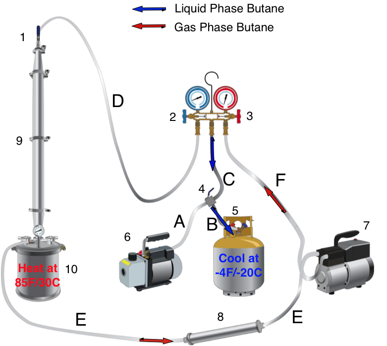
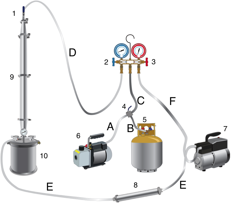
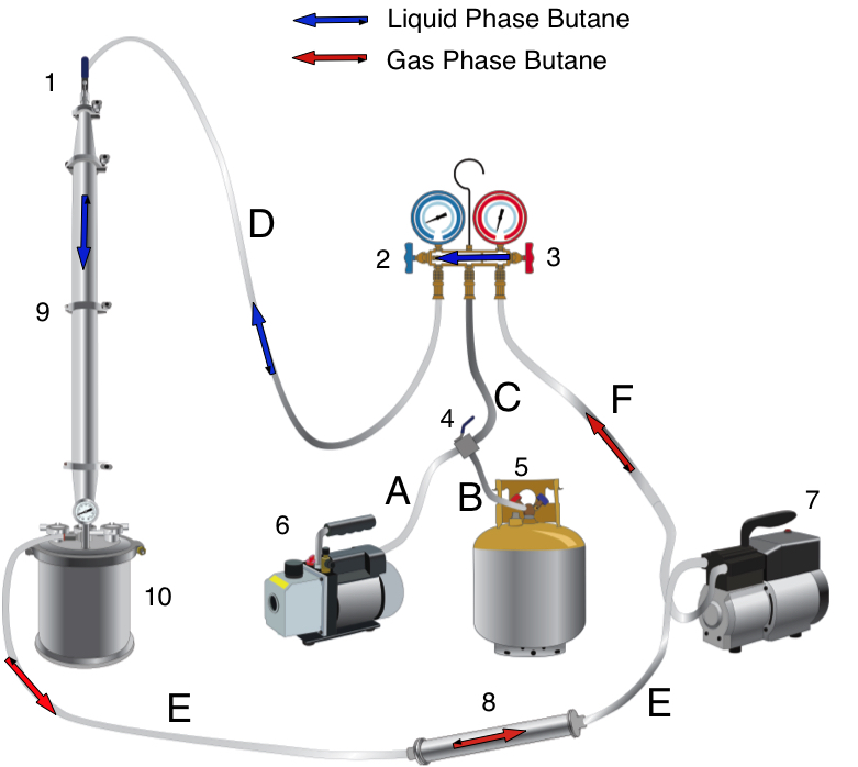
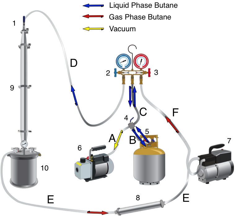
Continuous Shower – a top down shower of butane over a column packed with plant material. The butane is recycled from the extractor collection chamber in the gas phase. It is pumped through the recovery pump (RP) and passes through the condensing coil (CC). The butane changes from the gas phase to liquid phase, and passes through the recovery manifold (RM), and back through the top of the column. The plant material is then “continuously” showered with cold liquid butane. This strips the plant material of all its butane soluble molecules – i.e. cannabinoids, terpenes, and plant lipids/waxes

Cooling Bath – a mixture of ice and water or dry ice and ethanol that is used to cool down extractor components like the recovery cylinder (RC)

Fractions – different grades of trichomes/hash depending on amount of plant material contamination.

Gas Phase – butane is a gas

“Hg or inches Hg – signifies the vacuum pressure of the system in “inches” of mercury.Maximum vacuum is 29”Hg while zero vacuum is 0”Hg. It’s a way of describing negative pressure, just like MPa (metric system measurement – mega Pascals), KPSI (standard/US system measurement – thousands of Pounds Per Square Inch), or bar/atm (metric measurement – the pressure in terms of the number of atmospheres)

Liquid Phase – butane is a liquid

Risk based approach – examining the inherent risks involved in a process and eliminating risks to improve the product safety or process safety.

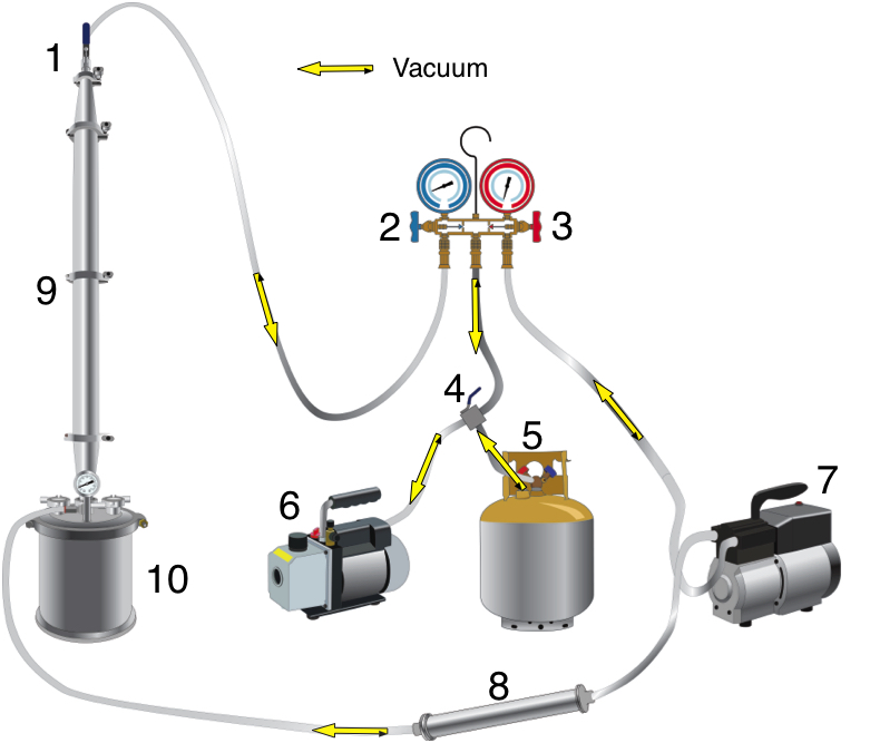
Vacuum – the vacuuming step is the first step in preparing the system for extraction. It is necessary to vacuum the extractor for two reasons. First it creates negative pressure that pulls the butane into the extractor. Second, it removes the majority of the atmospheric oxygen in order to prevent conditions where butane can ignite – remember that butane needs oxygen in order to combust.

Winterization – the process that removes plant lipids/waxes from an extract.

Component Terms:

Condensing/cooling Coil (CC) – a stainless steel coiled tube that acts as a heat exchanger. As butane gas passes into it, it cools down the gas and it changes over to the liquid phase – this is called a phase change of matter.

Dewaxing Column – a column that has cooling capabilities with dry ice and ethanol. It typically requires a 1 hour soak time to achieve dewaxing, although the process is often incomplete if not done under the proper conditions.

Gaskets – Buna, Viton, or PTFE “rings” that are placed between two sanitary fittings

High Pressure Side Recovery Manifold – the red side gauge and valve that opens and closes to allow gaseous butane to flow in to the manifold. The gas can be condensed into the liquid phase by maintaining a pressure of 100PSI and can be diverted back out the low pressure side or back into the recovery cylinder.

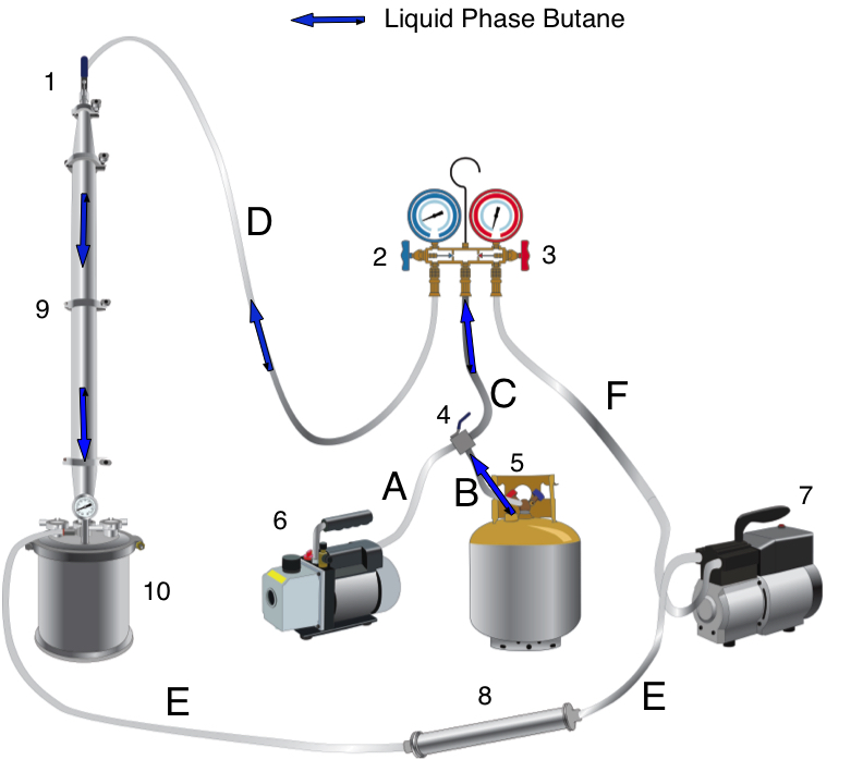
Low Pressure Side Recovery Manifold – the blue side gauge and valve, that opens and closes to allow liquid butane to flow into the extraction column.

Recovery Cylinder Liquid Side Valve – the valve (either blue or red) that has “LIQUID” printed on it. This valve opens up the extraction system to liquid butane. Different manufacturers have different conventions, so don’t assume you have the liquid side just because it’s blue.

Recovery Cylinder Liquid Straw – the tube that is attached to the recovery cylinder liquid side needle valve. The straw allows liquid butane to flow into through the valve into the extraction system.

Sanitary Fittings – individual pieces that make up the stainless steel columns and spools. Pieced together, they make the extraction column and extractor collection chamber. Sanitary fittings are held together by high-pressure triclamps


As always, if you have any questions please post them in the comments section. Your questions and time are valuable and we will make every attempt to help you through your process.