GMP Cannabis vs. Extraction content on HempHacker

Last week I sent out a survey to subscribers on the HempHacker email list. The goal was to find what content interests readers the most. The numbers and comments speak for themselves. Overall, everyone loves actionable content, but they would also like to see more blog posts about what’s going on at HempHacker.

The people’s choice is extraction content. If the people will have it, it shall be done. However, I am looking for an experienced writer and cannabis alchemist to join the HempHacker team to write for the crowd. My time is being placed mostly on Good Manufacturing Practices (GMP) consulting lately, and I haven’t been able to focus on extraction content.

I received some very helpful constructive criticism, which I greatly appreciate. It helps me understand how I could do my job better. It’s slightly difficult to scale it for all situations since there are different variables for each system, but I understand the need for specific parameters in doing extractions. I will work to improve this.

64% want more extraction content

  • New extraction techniques on the market
    • Wiped film evaporation
    • Short path distillation
  • Specific parameters for supercritical extractions – i.e. useable parameters
    • Amounts to be extracted
    • Solvents used
    • Temperatures
    • Pressures
  • Solventless extractions
  • SFE vs BHO comparisons

36% want more GMP Cannabis related content

  • How to establish GMP systems in your facility
  • GMP Training
  • Good Documentation Practices (GDP)
  • Quality Assurance (QA) and Quality Control (QC) Practices

While I understand the majority want to see more extraction content, GMP consulting pays the bills, and is my primary focus. I really hope that the GMP Cannabis content will also be useful to people doing extractions. It is the definite future of the industry, and I would like to help everyone learn the practices before the FDA regulates the production and processing of cannabis and its extracts.

Thank you to everyone who participated in the survey. Your feedback is very useful to me. As usual, you have an open line of communication to me at andrew@hemphacker.com.

-Andrew

https://patents.google.com/patent/US8530679B2/en?q=thc&q=butane&q=cannabis

In 2007, a patent was filed for delta-9 THC processing. It covered a range of organic solvents with boiling points preferably below 0C – ie “low boiling point solvents.” This fits the description of several hydrocarbons – the author preferred isobutylene, propane, butane, and cyclobutane.

This patent was validated with very pure THC – from 95-99% – nearly reagent grade. So while it validates the situation in under perfect laboratory conditions, it does not reflect the true extraction conditions that happen every day for medical and recreational extractions.

The important points of this patent are the temperatures. The desired solvent exists as a gas at room temperature, but can be in the liquid phase when put under pressure and temperature constraints. Controlled temperatures not only dictate the phase of the hydrocarbons (i.e. gas or liquid), but also prevent degradation of cannabinoids, preserve terpenes, and reduce solubility of plant lipids.

Some side notes on the choice of solvents were low toxicity, low environmental impact, and generally recognized as safe for use in pharmaceutical applications. These factors combined are some of the reason for using propane and butane as the industry standard for cannabis extractions.

That covers the theory behind the process. Below you’ll find a few points on the methods that make this a very good process.

Assuming one has an understanding of the standard closed loop extraction process, you can imagine how this process goes. You’ve passed your butane/propane through the extraction column and the extract is sitting in the collection vessel.

It does not specifically say in the patent, but there are two ways this could go. The first option is that the butane is boiled off (reclaimed) to a certain percentage, and then transferred to a secondary container. The second is that the butane is allowed to boil off without care for reclaiming. I find the second option less likely, but it is a possibility.

Assuming the first option, the partially purged extract is transferred to a second collection chamber while it is still of high enough viscosity. This process is called a cannula transfer. The second collection vessel is where there are inert conditions, and the butane/propane is evaporated off.

Solvent is evaporated by increasing the temperature of the second collection vessel and passing inert gas over the surface of the extract – in this case, I’m almost sure the author used a side-arm round bottom flask. I’ve covered the value of inert gasses in a few of my posts at Hemphacker, but it is definitely a standard operating procedure in a chemistry laboratory. In this case, they use argon gas to assist the removal of butane from the extract.

Using inert gas helps remove the solvent by changing the dynamics of partial pressures at the surface of the solution – this is a long topic and out of the scope of this article. However, the change in partial pressure increases the rate of evaporation for butane and allows one to to reduce the temperature to 4C, from what would normally be done at much higher purging temperatures. Now we’re in terpene preservation territory.

The low temperatures are beneficial because it reduces the degradation of the cannabinoids, and also keeps the terpenes in a low-volatility condition. In addition, the author claims that these temperatures make it easier to handle the extract.

As a result of evaporating off propane/butane at a lower temperature, the author claims that the invention induces a more crystalline form of the extract rather than the formation of a homogenous solid. I would hypothesize that the slow cool temperatures allow crystal formation, in what is a more gentle process that does not disrupt the nucleation of seed crystals. They claim to have shown this by x-ray diffraction, but no data is given to supplement the claim. Still, the extract is not 100% crystalline, as claimed by the author; as an analogy, think of how some parts of an extract will auto-butter before others.

One point to keep in mind is that this is a pure starting material, for the sake of explaining the invention of the process. By experience, a chemist performing extractions knows that the results vary by strain to strain, because of the different distribution of cannabinoids and terpenes.

This is a fundamental patent to understand the origins of live resin extractions. This author has several more patents on the subject, but I chose to write about this one because it was the “first mover.” The cannabis community owes much thanks to pioneers in science, who laid the way for us to preserve the ultimate essence of the plant.
I hope that you all find this interesting. Please share your thoughts and comments!

When the extractor has been properly shut down, it’s time to disassemble it and reveal the cannabinoid alchemy you’ve performed, turning solid green plant matter into a concentrated liquid gold $)

Final image - Shut down

Step 7 – Extractor Disassembly – remove stainless steel hose (D) from extractor column valve (1)
Component #Component NameAbbreviationOpen/OnClosed/Off
1Extraction Column ValveECVx
2Low Pressure Recovery ManifoldRM2x
3High Pressure Recovery ManifoldRM3x
4Purge PortPPx
5Recovery CylinderRCx
6Vacuum PumpVPx
7Recovery PumpRPx
Step 7.1 – Extractor Disassembly – open extractor column valve (1) to allow air to enter extractor
Component #Component NameAbbreviationOpen/OnClosed/Off
1Extraction Column ValveECVx
2Low Pressure Recovery ManifoldRM2x
3High Pressure Recovery ManifoldRM3x
4Purge PortPPx
5Recovery CylinderRCx
6Vacuum PumpVPx
7Recovery PumpRPx
Step 7.2 – Extractor Disassembly – remove extraction column (11)
Component #Component NameAbbreviationOpen/OnClosed/Off
1Extraction Column ValveECVx
2Low Pressure Recovery ManifoldRM2x
3High Pressure Recovery ManifoldRM3x
4Purge PortPPx
5Recovery CylinderRCx
6Vacuum PumpVPx
7Recovery PumpRPx
Step 7.3 – Extractor Disassembly – remove extractor base from extractor collection vessel (12)
Component #Component NameAbbreviationOpen/OnClosed/Off
1Extraction Column ValveECVx
2Low Pressure Recovery ManifoldRM2x
3High Pressure Recovery ManifoldRM3x
4Purge PortPPx
5Recovery CylinderRCx
6Vacuum PumpVPx
7Recovery PumpRPx


As always, if you have any questions please post them in the comments section. Your questions and time are valuable and we will make every attempt to help you through your process.

Once the extraction collection chamber reaches the desired pressure under vacuum, it’s ready to shut down. Shut down always starts with stopping the flow of butane – i.e. turning off the recovery pump.

Final image - Shut down

Step 6 – Post Recovery Shut Down – turn off the recovery pump (7)
Component #Component NameAbbreviationOpen/OnClosed/Off
1Extraction Column ValveECVx
2Low Pressure Recovery ManifoldRM2x
3High Pressure Recovery ManifoldRM3x
4Purge PortPPx
5Recovery CylinderRCx
6Vacuum PumpVPx
7Recovery PumpRPx
Step 6.1 – Post Recovery Shut Down – close the recovery cylinder liquid side valve (5)
Component #Component NameAbbreviationOpen/OnClosed/Off
1Extraction Column ValveECVx
2Low Pressure Recovery ManifoldRM2x
3High Pressure Recovery ManifoldRM3xx
4Purge PortPPx
5Recovery CylinderRCx
6Vacuum PumpVPx
7Recovery PumpRPx
Step 6.2 – Post Recovery Shut Down – close the purge port (4)
Component #Component NameAbbreviationOpen/OnClosed/Off
1Extraction Column ValveECVx
2Low Pressure Recovery ManifoldRM2x
3High Pressure Recovery ManifoldRM3xx
4Purge PortPPx
5Recovery CylinderRCx
6Vacuum PumpVPx
7Recovery PumpRPx
Step 6.3 – Post Recovery Shut Down – close the high pressure recovery manifold (3)
Component #Component NameAbbreviationOpen/OnClosed/Off
1Extraction Column ValveECVx
2Low Pressure Recovery ManifoldRM2x
3High Pressure Recovery ManifoldRM3x
4Purge PortPPx
5Recovery CylinderRCx
6Vacuum PumpVPx
7Recovery PumpRPx
Step 6.4 – Post Recovery Shut Down – close the extraction column valve (1)
Component #Component NameAbbreviationOpen/OnClosed/Off
1Extraction Column ValveECVx
2Low Pressure Recovery ManifoldRM2x
3High Pressure Recovery ManifoldRM3x
4Purge PortPPx
5Recovery CylinderRCx
6Vacuum PumpVPx
7Recovery PumpRPx


As always, if you have any questions please post them in the comments section. Your questions and time are valuable and we will make every attempt to help you through your process.

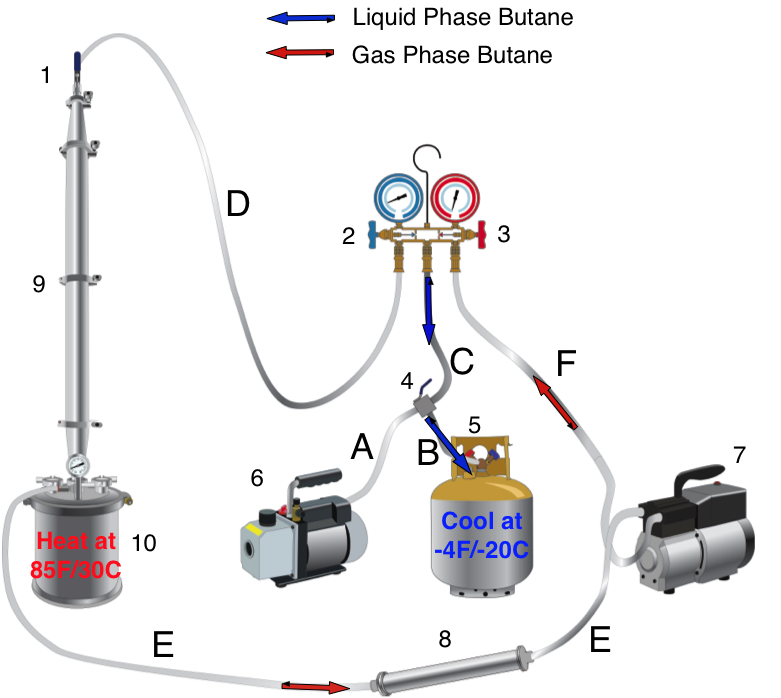
After running the continuous shower, the liquid butane is pulled off into the gas phase by the recovery pump and pushed into the liquid phase, which then fills back into the recovery cylinder. The push/pull method of recovery requires heating the extraction collection vessel (10) and cooling the recovery cylinder (5). The recovery cylinder can be cooled to -50C if you use a dry ice/ethanol bath, but is not necessary – it just speeds up the recovery. Push/pull is governed by the most useful branch of chemistry – thermodynamics – we’ll explain that at a later time if anyone is interested…

Final image - butane recovery

Step 5 – Butane Recovery – heat extraction collection chamber (10) to 85F/30C; cool the recovery cylinder (5) to -4F/-20C; open the purge port (4)
Component #Component NameAbbreviationOpen/OnClosed/Off
1Extraction Column ValveECVx
2Low Pressure Recovery ManifoldRM2x
3High Pressure Recovery ManifoldRM3x
4Purge PortPPx
5Recovery CylinderRCx
6Vacuum PumpVPx
7Recovery PumpRPx
Step 5.1 – Butane Recovery – open the recovery cylinder liquid side valve (5) and simultaneously turn on the recovery pump (7)
Component #Component NameAbbreviationOpen/OnClosed/Off
1Extraction Column ValveECVx
2Low Pressure Recovery ManifoldRM2x
3High Pressure Recovery ManifoldRM3x
4Purge PortPPx
5Recovery CylinderRCx
6Vacuum PumpVPx
7Recovery PumpRPx
Step 5.2 – Butane Recovery – open the recovery cylinder liquid side valve (5) and simultaneously turn on the recovery pump (7)
Component #Component NameAbbreviationOpen/OnClosed/Off
1Extraction Column ValveECVx
2Low Pressure Recovery ManifoldRM2x
3High Pressure Recovery ManifoldRM3x
4Purge PortPPx
5Recovery CylinderRCx
6Vacuum PumpVPx
7Recovery PumpRPx
Step 5.3 – Butane Recovery – recover butane until the pressure gauge reads 10″Hg to 22″Hg
Component #Component NameAbbreviationOpen/OnClosed/Off
1Extraction Column ValveECVx
2Low Pressure Recovery ManifoldRM2x
3High Pressure Recovery ManifoldRM3x
4Purge PortPPx
5Recovery CylinderRCx
6Vacuum PumpVPx
7Recovery PumpRPx


As always, if you have any questions please post them in the comments section. Your questions and time are valuable and we will make every attempt to help you through your process.

After the desired amount of time running the continuous shower, the process needs to be shut down. The process can transition directly to the recovery step, but first make sure that no unsafe conditions exist. Since this puts several pounds of butane into the recovery cylinder, the process is inherently dangerous. Take your time and make sure every valve is open or closed as it should be.

Final image - Shut down

Step 4 – Continuous Shower – turn off the recovery pump (7)
Component #Component NameAbbreviationOpen/OnClosed/Off
1Extraction Column ValveECVx
2Low Pressure Recovery ManifoldRM2x
3High Pressure Recovery ManifoldRM3x
4Purge PortPPx
5Recovery CylinderRCx
6Vacuum PumpVPx
7Recovery PumpRPx
Step 4.1 – Continuous Shower Shutdown – close the low pressure recovery manifold (2)
Component #Component NameAbbreviationOpen/OnClosed/Off
1Extraction Column ValveECVx
2Low Pressure Recovery ManifoldRM2x
3High Pressure Recovery ManifoldRM3x
4Purge PortPPx
5Recovery CylinderRCx
6Vacuum PumpVPx
7Recovery PumpRPx


As always, if you have any questions please post them in the comments section. Your questions and time are valuable and we will make every attempt to help you through your process.

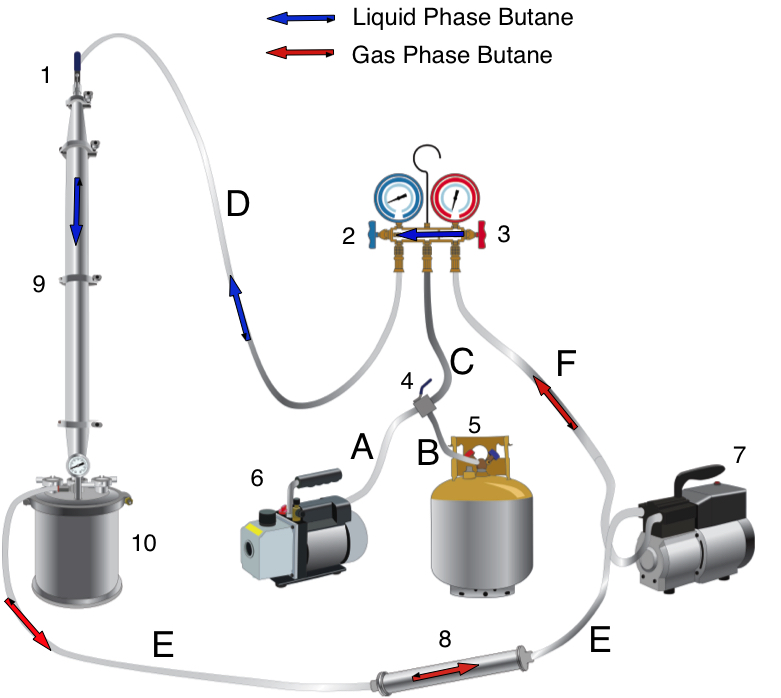
Continuous showers are the easiest and most efficient way to extract cannabinoids in a CLS. The butane is recycled by being pulled out of the bottom of the collection chamber, in the gas phase. It then passes through the recovery pump, up the the recovery manifold, and is condensed into the liquid phase by keeping the high pressure side of the recovery manifold (3) at ~100PSI.

Final image - Continuous Shower

Step 3 – Continuous Shower – open the high pressure recovery manifold (3)
Component #Component NameAbbreviationOpen/OnClosed/Off
1Extraction Column ValveECVx
2Low Pressure Recovery ManifoldRM2x
3High Pressure Recovery ManifoldRM3x
4Purge PortPPx
5Recovery CylinderRCx
6Vacuum PumpVPx
7Recovery PumpRPx
Step 3.1 – Continuous Shower – turn on recovery pump (RP) and run the continuous shower for 5-45 minutes – maintain a pressure of ~100 PSI on the high pressure side of the recovery manifold
Component #Component NameAbbreviationOpen/OnClosed/Off
1Extraction Column ValveECVx
2Low Pressure Recovery ManifoldRM2x
3High Pressure Recovery ManifoldRM3x
4Purge PortPPx
5Recovery CylinderRCx
6Vacuum PumpVPx
7Recovery PumpRPx


As always, if you have any questions please post them in the comments section. Your questions and time are valuable and we will make every attempt to help you through your process.

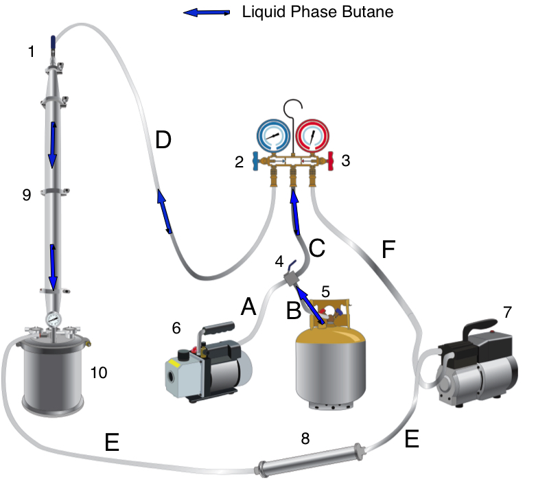
Once the extractor has reached maximum vacuum and no leaks have been detected, it can be filled with butane.

Final image - Filling

Step 2 – Fill the extractor – open recovery cylinder liquid side valve
Component #Component NameAbbreviationOpen/OnClosed/Off
1Extraction Column ValveECVx
2Low Pressure Recovery ManifoldRM2x
3High Pressure Recovery ManifoldRM3x
4Purge PortPPx
5Recovery CylinderRCx
6Vacuum PumpVPx
7Recovery PumpRPx
Step 2.1 – Fill the extractor – open purge port (4)
Component #Component NameAbbreviationOpen/OnClosed/Off
1Extraction Column ValveECVx
2Low Pressure Recovery ManifoldRM2x
3High Pressure Recovery ManifoldRM3x
4Purge PortPPx
5Recovery CylinderRCx
6Vacuum PumpVPx
7Recovery PumpRPx
Step 2.2 – Fill the extractor – open the low pressure recovery manifold (2)
Component #Component NameAbbreviationOpen/OnClosed/Off
1Extraction Column ValveECVx
2Low Pressure Recovery ManifoldRM2x
3High Pressure Recovery ManifoldRM3x
4Purge PortPPx
5Recovery CylinderRCx
6Vacuum PumpVPx
7Recovery PumpRPx
Step 2.3 – Fill the extractor – open the extraction column valve (1) and allow butane to fill the extractor until 45 PSI or the butane stops flowing
Component #Component NameAbbreviationOpen/OnClosed/Off
1Extraction Column ValveECVx
2Low Pressure Recovery ManifoldRM2x
3High Pressure Recovery ManifoldRM3x
4Purge PortPPx
5Recovery CylinderRCx
6Vacuum PumpVPx
7Recovery PumpRPx
Step 2.4 – Fill the extractor – when butane stops flowing, close the recovery cylinder liquid side valve (5)
Component #Component NameAbbreviationOpen/OnClosed/Off
1Extraction Column ValveECVx
2Low Pressure Recovery ManifoldRM2x
3High Pressure Recovery ManifoldRM3x
4Purge PortPPx
5Recovery CylinderRCx
6Vacuum PumpVPx
7Recovery PumpRPx
Step 2.5 – Fill the extractor – close purge port (4)
Component #Component NameAbbreviationOpen/OnClosed/Off
1Extraction Column ValveECVx
2Low Pressure Recovery ManifoldRM2x
3High Pressure Recovery ManifoldRM3x
4Purge PortPPx
5Recovery CylinderRCx
6Vacuum PumpVPx
7Recovery PumpRPx


As always, if you have any questions please post them in the comments section. Your questions and time are valuable and we will make every attempt to help you through your process.

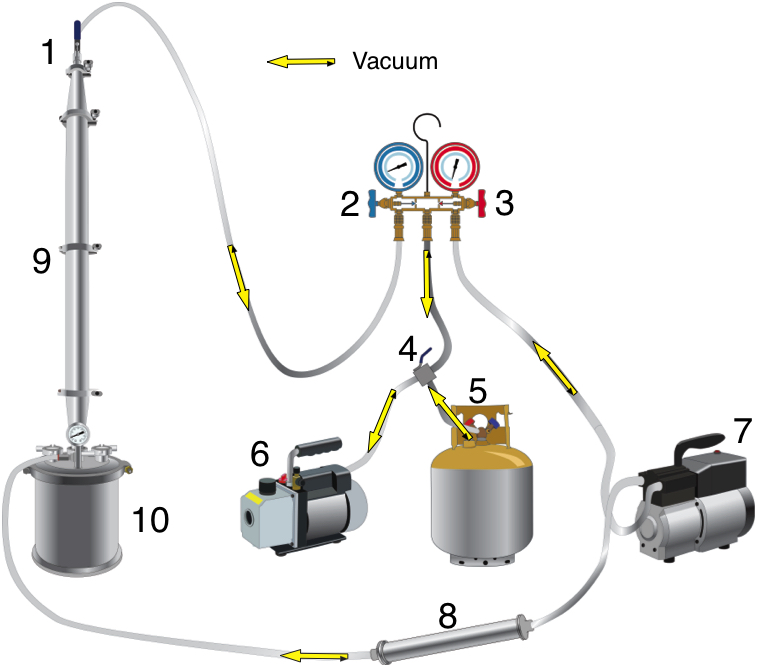
There are two reasons to vacuum the extractor: 1. create negative pressure to “pull” the butane into the extractor; 2. remove oxygen from the extractor to prevent potential explosive conditions. Follow the steps below. One step at a time, you vacuum out each segment of the extractor. The chart will show you the open/closed condition of every valve or on/off switch as you work through the steps. Final image - vacuum diagram

Step 1 – Pre-vacuum – turn on vacuum
Component #Component NameAbbreviationOpen/OnClosed/Off
1Extraction Column ValveECVx
2Low Pressure Recovery ManifoldRM2x
3High Pressure Recovery ManifoldRM3x
4Purge PortPPx
5Recovery CylinderRCx
6Vacuum PumpVPx
7Recovery PumpRPx
Step 1.1 – Vacuum – open purge port (4)
Component #Component NameAbbreviationOpen/OnClosed/Off
1Extraction Column ValveECVx
2Low Pressure Recovery ManifoldRM2x
3High Pressure Recovery ManifoldRM3x
4Purge PortPPx
5Recovery CylinderRCx
6Vacuum PumpVPx
7Recovery PumpRPx
Step 1.2 – Vacuum – close purge port (4) and open high pressure recovery manifold valve (3)
Component #Component NameAbbreviationOpen/OnClosed/Off
1Extraction Column ValveECVx
2Low Pressure Recovery ManifoldRM2x
3High Pressure Recovery ManifoldRM3x
4Purge PortPPx
5Recovery CylinderRCx
6Vacuum PumpVPx
7Recovery PumpRPx
Step 1.3 – Vacuum – close high pressure recovery manifold valve (3) and open low pressure recovery manifold valve (2)
Component #Component NameAbbreviationOpen/OnClosed/Off
1Extraction Column ValveECVx
2Low Pressure Recovery ManifoldRM2x
3High Pressure Recovery ManifoldRM3x
4Purge PortPPx
5Recovery CylinderRCx
6Vacuum PumpVPx
7Recovery PumpRPx
Step 1.4 – Vacuum – open extraction column valve (1)
Component #Component NameAbbreviationOpen/OnClosed/Off
1Extraction Column ValveECVx
2Low Pressure Recovery ManifoldRM2x
3High Pressure Recovery ManifoldRM3x
4Purge PortPPx
5Recovery CylinderRCx
6Vacuum PumpVPx
7Recovery PumpRPx
Step 1.5 – Vacuum – Vacuum extractor to the maximum vacuum (~29″Hg)
Component #Component NameAbbreviationOpen/OnClosed/Off
1Extraction Column ValveECVx
2Low Pressure Recovery ManifoldRM2x
3High Pressure Recovery ManifoldRM3x
4Purge PortPPx
5Recovery CylinderRCx
6Vacuum PumpVPx
7Recovery PumpRPx
Step 1.6 – Vacuum – close extraction column valve (1) and low pressure recovery manifold (2)
Component #Component NameAbbreviationOpen/OnClosed/Off
1Extraction Column ValveECVx
2Low Pressure Recovery ManifoldRM2x
3High Pressure Recovery ManifoldRM3x
4Purge PortPPx
5Recovery CylinderRCx
6Vacuum PumpVPx
7Recovery PumpRPx
Step 1.7 – Vacuum – Wait 10 minutes and observe all pressure gauges for pressure drop, then check one valve at a time for pressure drop
Component #Component NameAbbreviationOpen/OnClosed/Off
1Extraction Column ValveECVx
2Low Pressure Recovery ManifoldRM2x
3High Pressure Recovery ManifoldRM3x
4Purge PortPPx
5Recovery CylinderRCx
6Vacuum PumpVPx
7Recovery PumpRPx


As always, if you have any questions please post them in the comments section. Your questions and time are valuable and we will make every attempt to help you through your process.

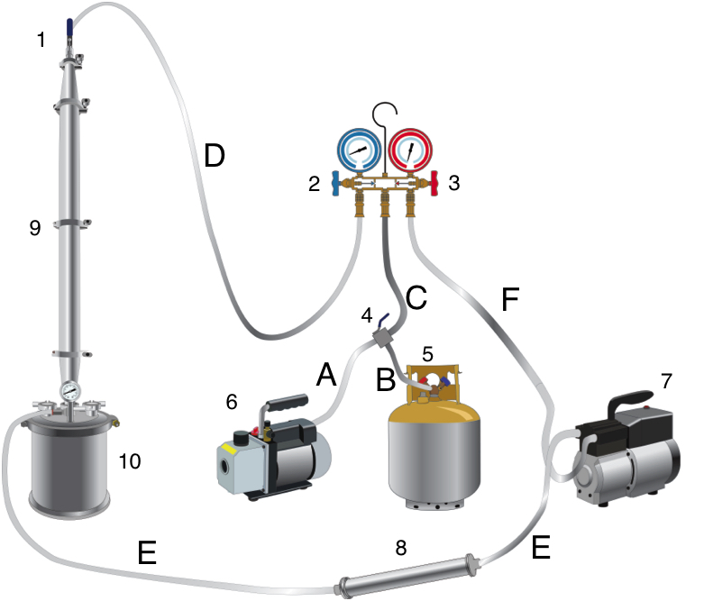
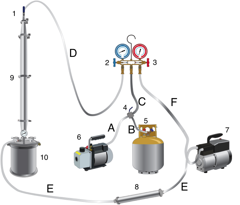
It is essential to understand the pathways of the different braided stainless steel lines lead to in order to understand the flow of the butane.

The best suggestion to learn this, is to visualize it. If you can picture it in your head, you can perform it on the extractor. By the time you’re done with this series of posts, you should be able to safely operate an extractor in both your mind as well as in reality.

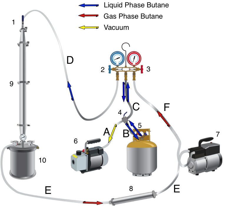
As will be explained in a later post, the high pressure side recovery manifold valve (3) is closed just far enough to keep ~100PSI. By keeping 100PSI, the gas phase butane is liquified because the pressure. That liquid butane can be cycled back through (D) into the extractor or it can pass through (C) and (B) back into the recovery cylinder.

Final image - plumbing diagram

Stainless Steel hoses
A6 to 4 – vacuum pump to purge port
B5 to 4 – recovery cylinder to purge port
C4 to 2/3 – purge port to recovery manifold
D2 to 1 – low pressure side recovery manifold to extraction column valve
E10 to 7 – extraction collection chamber to recovery pump
F7 to 3 – recovery pump to high pressure side recovery manifold


As always, if you have any questions please post them in the comments section. Your questions and time are valuable and we will make every attempt to help you through your process.